
Hybrid machine with hydraulic drive device

a technology of hydraulic drive and hybrid machine, which is applied in the direction of fluid coupling, servomotor, coupling, etc., can solve the problems of inability to perform energy recovery continuously, difficulty in estimating energy recovery in expressway traveling accompanied by infrequent braking,

Inactive Publication Date: 2005-11-08
KOMATSU LTD
View PDF19 Cites 100 Cited by
  • Summary
  • Abstract
  • Description
  • Claims
  • Application Information

AI Technical Summary

Benefits of technology

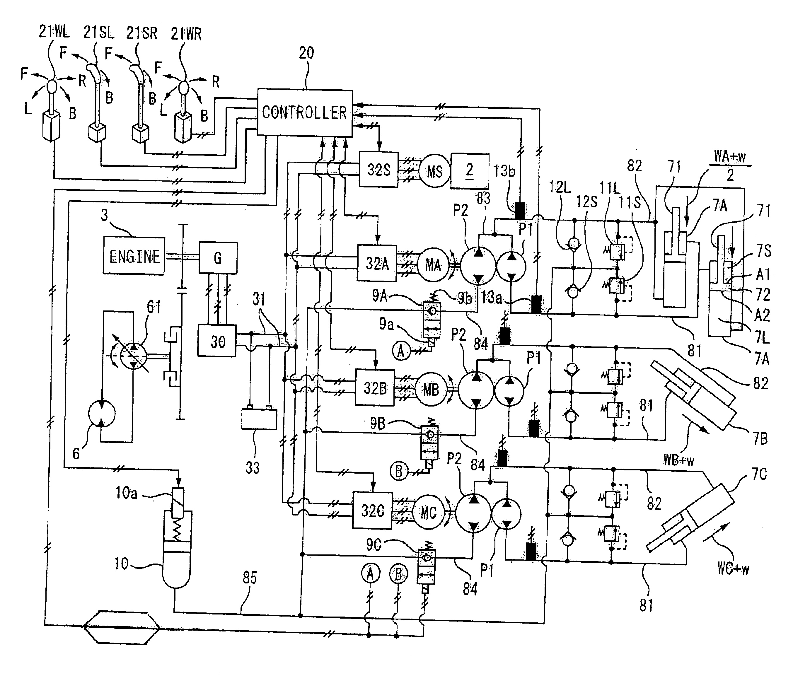
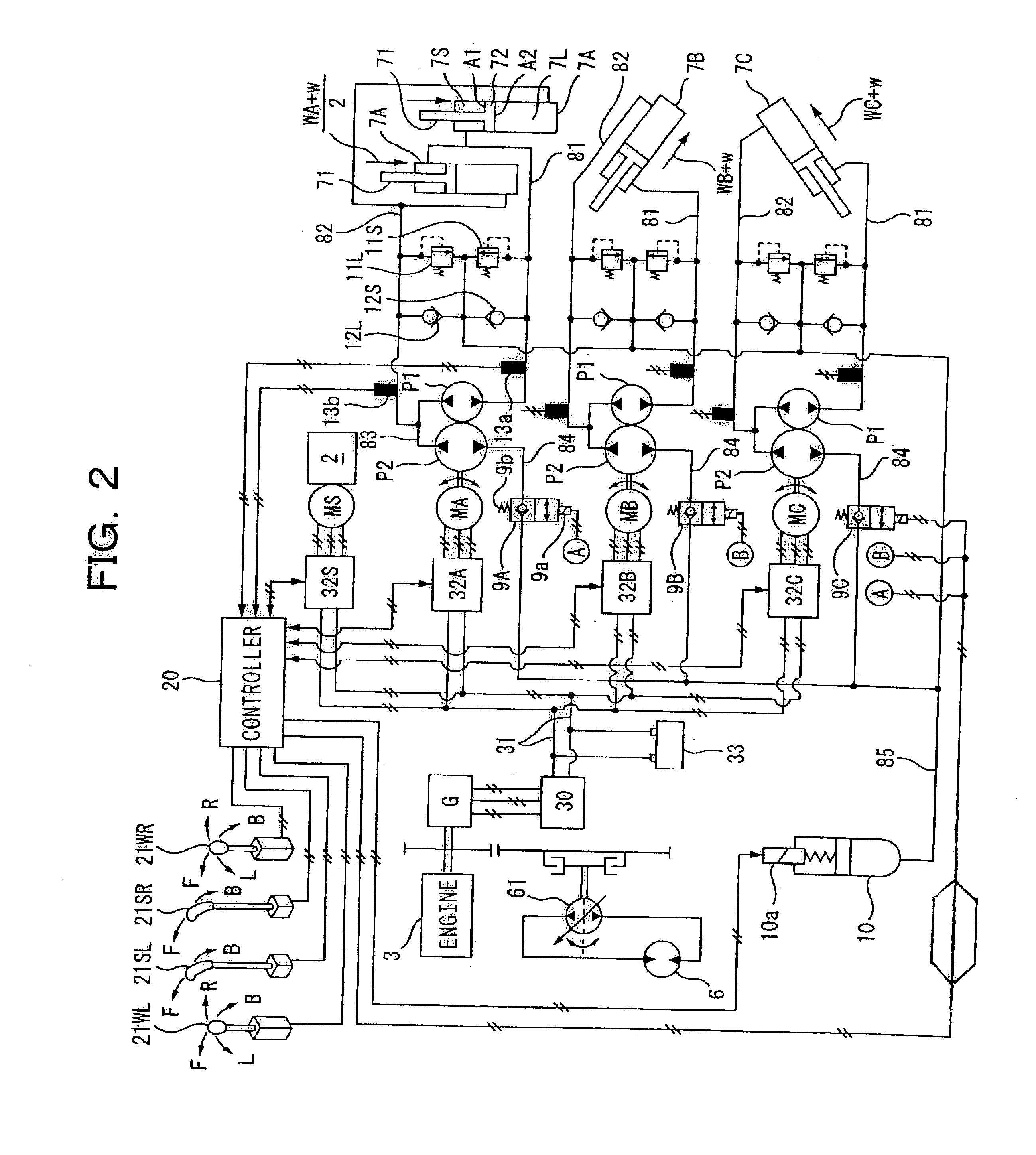
[0014]Incidentally, the first and second hydraulic pumps have the function of a direction switching valve in open circuits. The direction switching valve controls the flow rate with a throttling operation in addition to the switching of the flow direction of oil, and hence it involves throttling loss (heat loss). However, the flow rate control by the first and second hydraulic pumps in the first constitution is performed by only driving of the first and second pumps, whereby no throttling loss occurs, thus producing an energy saving effect. Needless to say, since there is no direction switching valve, an economic effect is produced correspondingly.
[0037]According to such a ninth constitution, negative pressure is generated in the first and second passages when the first and second hydraulic pumps are rotated in the mutual variability of volumetric efficiency of the first and second hydraulic pumps and when the hydraulic cylinder is extended / contracted by the external load when the fist and second hydraulic pumps are stopped. However, when the oil pressures of the first and second passages are going to become equal to or lower than a pressure in the accumulator, the first and second check valves are opened to allow the first and second passages to communicate with the accumulator and allow the respective oil pressures of the first and second passages to become the same as the pressure in the accumulator. Accordingly, the occurrence of cavitation and aeration in the first and second passages can be prevented.

Problems solved by technology

Incidentally, energy recovery of storing the electromotive force based on the reverse driving of the electric motor in the second battery in the ordinary vehicle can be expected in city traveling accompanied by frequent braking, but it is difficult to expect the energy recovery in expressway traveling accompanied by infrequent braking.
Namely, according to this hybrid ordinary vehicle, the energy recovery cannot be performed constantly.

Method used


Image

  • Hybrid machine with hydraulic drive device
  • Hybrid machine with hydraulic drive device
  • Hybrid machine with hydraulic drive device

Examples


Embodiment Construction

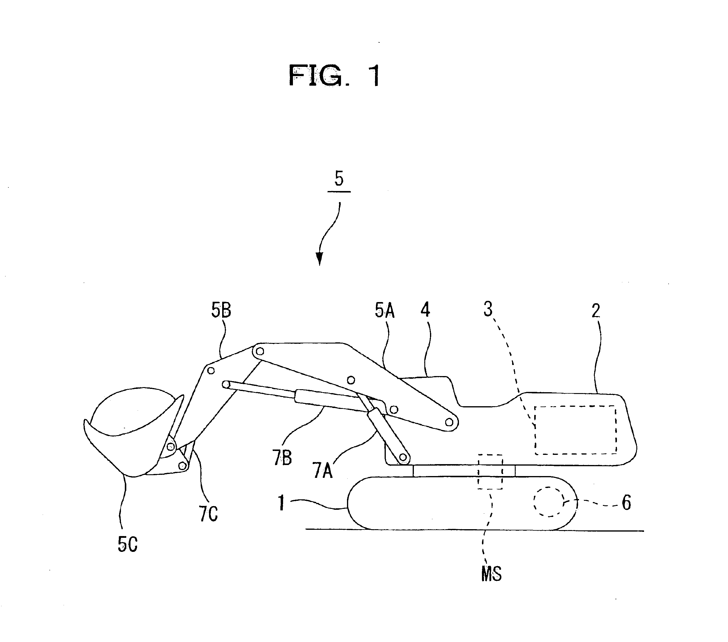
[0076]Preferred embodiments of a hydraulic circuit for driving a hydraulic cylinder according to the present invention will be explained with reference to FIG. 1 to FIG. 29.

[0077]A machine as an example equipped with a first embodiment is a loading shovel in FIG. 1. This loading shovel includes a superstructure 2 rotatably on a base carrier 1, and includes an engine 3, an operator's cab 4, and a working machine 5 on the superstructure 2. The base carrier 1 is allowed to move forward and backward, stop, and operate by hydraulic motors 6 and 6 (hereinafter referred to as “traveling motors 6”) provided on both sides respectively. Generally, the superstructure 2 is conventionally allowed to normally and reversely rotate and stop by the hydraulic motors, but in the machine as the example, it is allowed to normally and reversely rotate and stop by an electric motor MS. The working machine 5 is allowed to operate (rise and lower, and bend) by the articulation of a boom 5A, an arm 5B, and a...


PUM


Abstract

A hybrid machine with a hydraulic drive device having hydraulic actuators allowed to operate against and by external loads is provided. To this end, the hybrid machine comprises hydraulic cylinders (7), first hydraulic pumps (P1) connected, with closed circuits, to head side pressure receiving chambers (7S) and bottom side pressure receiving chambers (7L) of the hydraulic cylinders (7), and second hydraulic pumps (P2) connected, with open circuits, to the bottom side pressure receiving chambers (7L) and an external oil chamber (10), wherein the first and second hydraulic pumps (P1, P2) are connected to electric motors (M) so as to be driven.

Description

TECHNICAL FIELD[0001]The present invention relates to a hybrid machine with a hydraulic drive device.BACKGROUND ART[0002]A hybrid machine, roughly speaking, includes an engine, a generator with the engine as a drive source, an electric motor, and a secondary battery for storing electromotive force of the electric motor generated by reverse driving of the electric motor by an external load, in which the electric motor receives electric power from the generator and the secondary battery so as to be driven. Hybridization aims at saving of energy and a reduction in pollution, and in recent years, it has been put to practical use in an ordinary vehicle and achieves favorable results. The saving of energy results from regeneration of electromotive force based on the reverse driving of the electric motor generated when a vehicle is braked and goes downhill as driving electric power for the electric motor, and a reduction in the fuel consumption of the engine owing to this regeneration. Mea...

Claims


Application Information

Patent Timeline
IPC IPC(8): E02F9/22F15B1/00F15B1/02F15B11/00F15B7/00F15B21/08F15B21/00F15B21/14F15B11/17
CPCE02F9/2217E02F9/2228E02F9/2282E02F9/2285E02F9/2292F15B1/024F15B7/00F15B7/006F15B11/17F15B21/08F15B21/14F15B2211/20576F15B2211/212F15B2211/27F15B2211/30515F15B2211/6309F15B2211/6313F15B2211/6651F15B2211/785B60L1/20B60L2200/40
Inventor HIRAKI, HIKOSABUROITOW, KOICHIROINOUEO, HIROAKI
Owner KOMATSU LTD
Learn More