Armour constructions

a technology of armour and construction, applied in the field of armour construction, can solve the problems of losing a large amount of penetration effect, and achieve the effect of reducing the penetration

Inactive Publication Date: 2005-11-08
BAE SYSTEMS PLC
View PDF4 Cites 29 Cited by
  • Summary
  • Abstract
  • Description
  • Claims
  • Application Information

AI Technical Summary

Benefits of technology

[0007]It has been found that a panel which is assembled so that the reactive explosion is greater at one edge of the panel than the opposite edge and / or so that the interior and exterior armour plates are restrained so that they are forced apart with a “peeling” effect by the reactive explosion has, when the panels is correctly mounted in use, advantages over known applique armour panels. One advantage of the present invention is that more reactive armour material is introduced into the shaped charge jet and the erosion of the jet is thereby increased on a weight by weight basis. Another known advantage of the present armour panel construction is that the semi-molten or plasma jet is deflected from its original attack angle reducing the ultimate angle of incidence.
[0008]The present invention provides an applique armour panel for fitting to a substrate and for protecting the substrate from missile or other projectile attack, which panel comprises an exterior plate, an interior plate and a layer of explosive material therebetween which explosive material is adapted to be detonated by an incoming missile or other projectile to cause the panel to disrupt the incoming missile or other projectile to reduce the penetrative effect thereof, the assembly of the panel being such that upon reactive explosion the interior and exterior plates are driven apart more rapidly at one edge of the panel than at an opposite edge by a rotating moment of one plate relative to the other thereby to enhance the disruptive effect upon the incoming missile or other projectile.
[0009]According to a feature of the invention restraining means may be provided to restrain the interior and exterior plates against being driven apart to a lesser degree at said one edge than at said opposite edge.
[0010]According to another feature of the invention the layer of explosive material may be substantially coextensive with the juxtaposed faces of said interior and exterior plates. In some constructions where such a full layer of explosive material is provided the layer of explosive material may be tapered so that it decreases in thickness in a direction extending from said one edge towards said opposite edge. In other constructions where such a full layer of explosive material is provided the layer of explosive material may be perforate, and in which the size of the perforations are graded so that they are of increased size in a direction extending away from said one edge towards said opposite edge. Preferably, the perforations are graded in rows.
[0011]In yet other constructions where a full layer of explosive material is provided an additional layer of explosive material may be superposed upon the first mentioned layer of explosive material so as to at least partially cover said first mentioned layer. In some panel assemblies the additional layer of explosive material may be perforate, and preferably the size of the perforations in said additional layer of explosive material are graded so that they are of increased size in a direction extending away from said one edge towards said opposite edge.
[0012]In other panel assemblies having an additional layer the additional layer of explosive material may be in the form of discrete strips, and preferably said strips are graded so that they are of decreasing width in a direction extending away from said one edge towards said opposite edge.

Problems solved by technology

When an incoming shaped charge warhead strikes explosive reactive armour at an oblique angle of attack, the movement of the metal plates across the line of the jet acts to erode and disrupt the jet, which thereby loses much of its penetrative effect.

Method used


Image

  • Armour constructions
  • Armour constructions
  • Armour constructions

Examples


Embodiment Construction

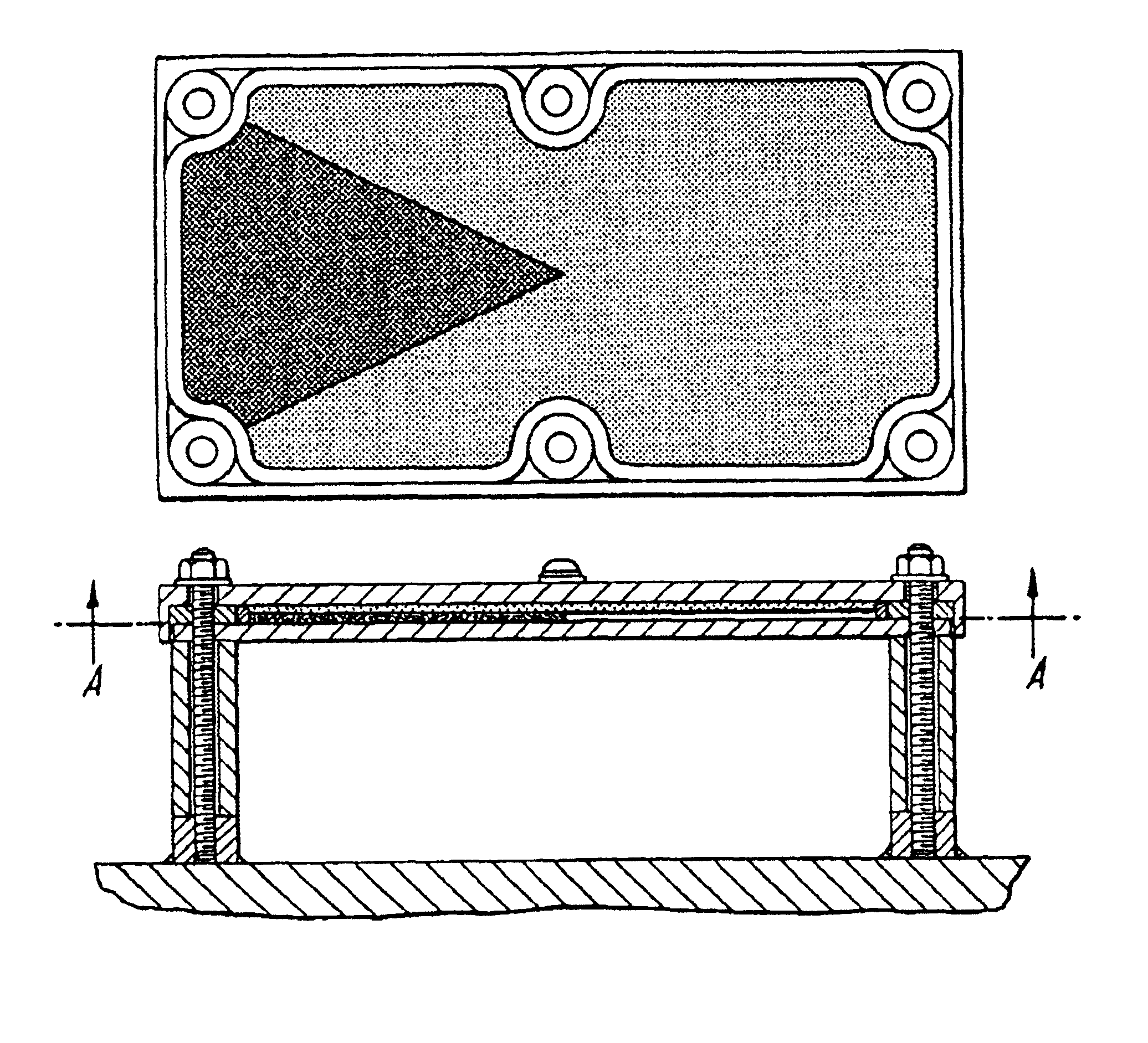
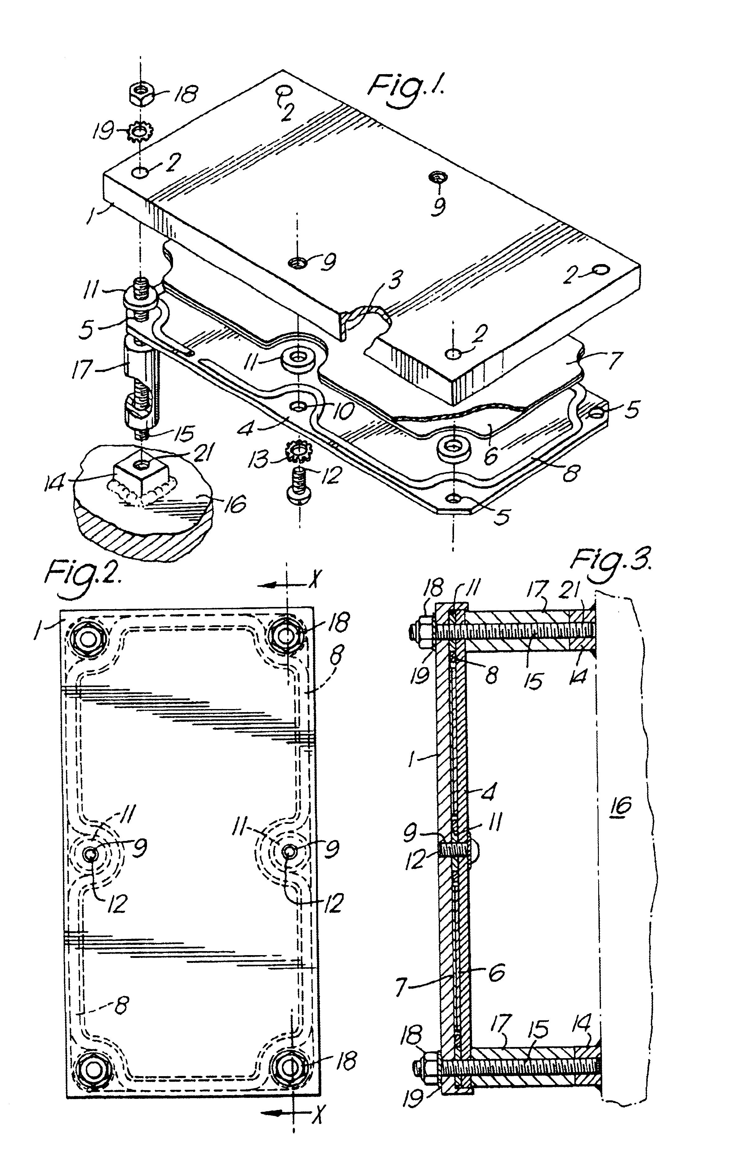
[0045]The ERA panel shown in FIG. 1-3 has a rectangular exterior plate 1 having four holes 2, one at each corner extending through the complete thickness of the exterior plate 1. The plate 1 has two additional holes 9 which are screw threaded and are located one each at the centre point of the two longer sides of the rectangular exterior plate 1. The plate 1 has an inward rim 3 around its entire edge, which extends perpendicular to the plane of the exterior plate 1 to form a recess on the inside surface of the plate 1. An interior plate 4 which is substantially rectangular with chamfered corners, is of a size such that it is an easy sliding fit within the rim 3 of the exterior plate 1.

[0046]The interior plate 4 has four holes 5 and two holes 10, which are in the same configuration and correspond exactly with the holes 2 and 9 respectively in the exterior plate 1 when the interior plate 4 is fitted within the rim 3.

[0047]FIG. 1 shows an approximately rectangular layer of explosive ma...


PUM


Abstract

An applique armour panel for fitting to a substrate and for protecting the substrate from missile or other projectile attack which panel comprises an exterior plate (1), an interior plate (4) and a layer or layers (7) of explosive material therebetween. The explosive material is detonated by an incoming missile to cause disruption of the incoming missile and reduce its penetrative effect. The panel is constructed so that upon reactive explosion the interior and exterior plates are driven apart more rapidly at one edge of the panel than at an opposite edge by a rotating moment of one plate relative to the other.

Description

BACKGROUND OF THE INVENTION[0001]1. Field of the Invention[0002]This invention relates to armour constructions and particularly to explosive reactive armour panel arrays that can be fixed at pre-determined locations on the outer surface of an armoured fighting or military vehicle, or other structure to be protected, to provide an additional protective layer around the outer surface of the vehicle or structure. Armour panels that can be mounted on an existing armoured vehicle or other existing structure are generally referred to as applique armours.[0003]2. Discussion of Prior Art[0004]Explosive reactive armour (ERA) comprises a protective construction having an explosive material which is detonated by the impact of an incoming projectile or missile to cause an explosion which reduces the penetrative effect of the projectile or missile. Usually the explosive material is located between metal plates which are driven apart by the explosion and it is the movement of these plates relativ...

Claims


Application Information

Patent Timeline
Patent Type & Authority Patents(United States)
IPC IPC(8): F41H5/013F41H5/00F41H5/007
CPCF41H5/007F41H5/013
Inventor JOHNSTON, CAMERON LINDSAYLEAMAN, PAUL STUART
Owner BAE SYSTEMS PLC
Why Eureka
Try Eureka