
Roller and sheet delivery unit

a technology of rolling and sheet paper, applied in the direction of shaft and bearing, thin material processing, article separation, etc., can solve the problems of inability to automatically deliver, unit blockage, and overlap amount to be readjusted, so as to achieve excellent flexibility and wear resistance, and reliably deliver sheets of paper

Inactive Publication Date: 2005-11-08
HITACHI OMRON TERMINAL SOLUTIONS CORP
View PDF7 Cites 10 Cited by
  • Summary
  • Abstract
  • Description
  • Claims
  • Application Information

AI Technical Summary

Benefits of technology

[0010]The present invention provides a roller having excellent wear resistance.
[0012]In addition, the invention provides a method of delivering sheets of paper without being affected by thicknesses or rigidities of the sheets to be conveyed. That is, it is another object of the invention to convey sheets of paper reliably if they are not uniform in thickness.
[0021]Furthermore, if a very hard member is used in the outer peripheral portion, the required displacement of the outer peripheral portion is obtained. As a result, a roller having excellent flexibility and wear resistance can be derived.
[0022]According to the sheet delivery unit of this invention, delivery of sheets of paper can be carried out reliably. It can also treat various kinds of sheets of paper ranging widely in rigidity and thickness.

Problems solved by technology

For example, where thick sheets of paper are used during a process where paper sheet processing equipment is fabricated, there is the drawback that the amount of overlap needs to be readjusted.
Furthermore, where a sheet of paper breaks and stays within a sheet delivery unit, if one tries to deliver the sheet, the unit may be clogged up because of increased thickness of the stacked sheets.
In this case, automatic delivery cannot be done and the currency fragments must be removed manually.
However, where sheets of different thicknesses or rigidities are treated, it is impossible to obtain stable separating action over all sheets of paper due to deformation.

Method used


Image

  • Roller and sheet delivery unit
  • Roller and sheet delivery unit
  • Roller and sheet delivery unit

Examples


Embodiment Construction

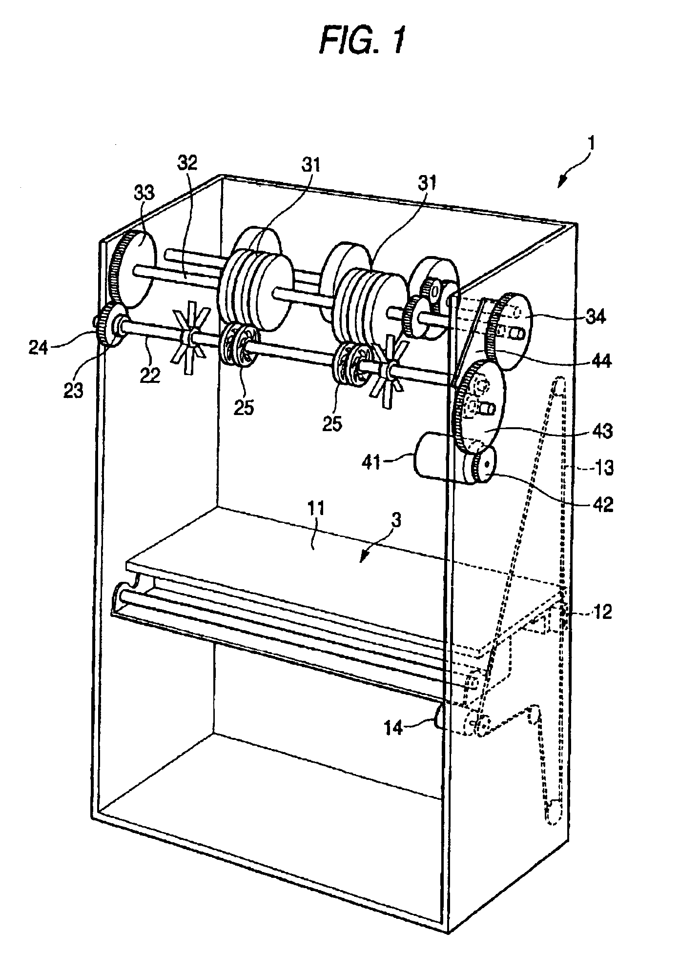
[0029]Embodiments of this invention are hereinafter described with reference to the drawings.

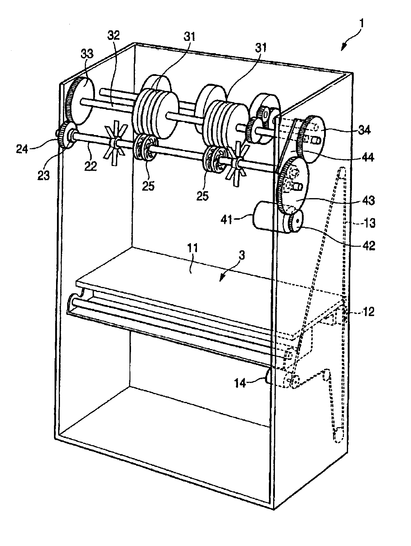
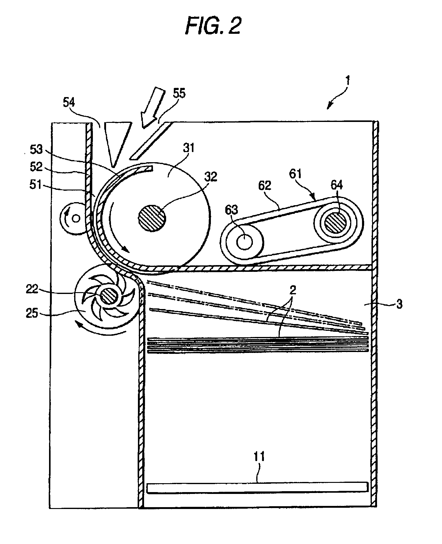
[0030]The perspective and structure of a paper currency collecting-and-delivering device 1 is first described by referring to FIGS. 1 and 2.

[0031]FIG. 1 is a perspective view of the paper currency collecting-and-delivering device 1. The contour of this device 1 is shaped like a box. The device 1 has an inner collection space 3 where paper currencies are stacked and collected. An elevating plate 11 having the same size as the currencies is mounted at the bottom of the collection space 3.

[0032]The elevating plate 11 is so guided that it can move up and down in a horizontal state. The elevating plate 11 is controllably moved up and down by rotating an elevating belt 13 forward and rearward by rotating force of a reversible motor 14, the belt 13 being firmly mounted at a firm mounting portion 12.

[0033]Cylindrical feed rollers 31 for conveying paper currencies in the direction of delivery or coll...


PUM

PropertyMeasurementUnit
Wear resistanceaaaaaaaaaa
Flexibilityaaaaaaaaaa
Widthaaaaaaaaaa

Abstract

The invention provides a roller having excellent flexibility and wear resistance. The invention also provides a sheet delivery unit equipped with this roller. The unit is prevented from being clogged up with sheets due to rigidities of the sheets. Also, simultaneous delivery of plural sheets is suppressed. The allowable range of rigidities of paper currencies and the allowable range of their widths can be extended. The roller has a central portion extending along an axis, an outer peripheral portion formed around the central portion and made of a resilient body, and plural helical ribs connecting together the central portion and the outer peripheral portion. Each rib consists of a resilient body. Each rib is so shaped as to thicken gradually from the central portion toward the outer peripheral portion.

Description

FIELD OF THE INVENTION[0001]The present invention relates to a roller used to deliver sheets of paper one by one from a stack and also to a sheet delivery unit using this roller.BACKGROUND OF THE INVENTION[0002]One known sheet delivery unit utilizes the overlap method as described in Japanese Patent JP-A-2000-203735 to deliver sheets one by one out of a stack of paper. Another known sheet delivery unit makes use of the retard method described in Japanese Patent JP-A-8-81079 for the same purpose.[0003]In the overlap method, a feed roller rotated at a feeding force to deliver sheets of paper and a gate roller that is brought to a standstill during delivery are made to overlap. A force is produced when sheets of paper are squeezed between the feed and gate rollers and become deformed wavily. Using this force, frictional force is produced between each sheet and the rollers. Thus, the sheets are separated one by one.[0004]The “overlap” means that where the feed roller has two grooves, fo...

Claims


Application Information

Patent Timeline
IPC IPC(8): B65H27/00B65H3/06
CPCB65H27/00B65H2401/111B65H2404/1122B65H2404/117B65H2701/1912B65H2404/1316B65H83/025B65H2403/942B65H31/10B65H29/14
Inventor MIZUNO, SHOSAWAYAMA, HIDEYUKI
Owner HITACHI OMRON TERMINAL SOLUTIONS CORP
Learn More