Electric rotating machine for vehicle

a technology of rotating machines and electric motors, applied in the direction of dynamo-electric components, supports/encloses/casings, magnetic circuit shapes/forms/construction, etc., can solve the problems of reduced output and efficiency, increased so as to improve output and efficiency, cost and manufacturing processes, and reduce the resistance of metallic terminals.

Inactive Publication Date: 2005-11-08
MITSUBISHI ELECTRIC CORP
View PDF15 Cites 7 Cited by
  • Summary
  • Abstract
  • Description
  • Claims
  • Application Information

AI Technical Summary

Benefits of technology

[0009]The present invention has been made to solve the above-discussed problems and has an object of reducing not only cost and manufacturing processes but also resistance of the metallic terminal in order to improve output and efficiency by interposing just a single metallic terminal between a lead wire of a stator and a three-phase output terminal.
[0010]An electric rotating machine for vehicle of the invention includes a rotor fixed onto a rotating shaft disposed in a housing, a stator core disposed opposite to the rotor, a stator winding wound around the stator core, and a three-phase output terminal to which a lead wire of the stator winding is connected. And the lead wire is connected to the three-phase output terminal through a single metallic terminal. As a result, not only cost and manufacturing processes but also resistance is reduced, and therefore output and efficiency are improved.

Problems solved by technology

Accordingly, a problem exists in that excessive cost and complicated manufacturing processes have been required.
Moreover, since there are metallic terminals formed by resin molding, a further problem exists in that combustion loss may occur if a large current passes through, and that resistance of the metallic terminal brings about reduction in both output and efficiency.

Method used


Image

  • Electric rotating machine for vehicle
  • Electric rotating machine for vehicle
  • Electric rotating machine for vehicle

Examples


embodiment 1

[0019]An embodiment of the present invention is hereinafter described with reference to the accompanying drawings.

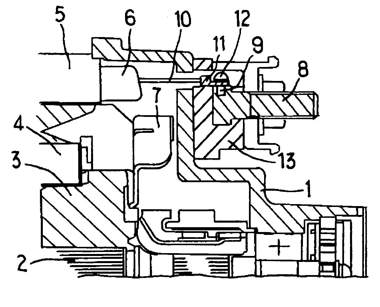
[0020]FIG. 1 is a partially sectional view showing an electric rotating machine for vehicle according to Embodiment 1 of the invention, and in which the electric rotating machine for vehicle starts an engine by acting as a motor and supplies power to the vehicle by acting as a generator.

[0021]In the drawing, numeral 1 designates a housing, numeral 2 designates a rotating shaft disposed in the housing 1 and numeral 3 designates a rotor fixed onto the rotating shaft 2. Numeral 4 designates a field winding wound around the rotor 3, numeral 5 designates a stator core disposed opposite to the rotor 3 and numeral 6 designates a stator winding wound around the stator core 5. Numeral 7 designates a cooling fan and numeral 8 designates a three-phase output terminal for taking out output from the stator.

[0022]Further, the three-phase output terminal 8 is provided with a threaded h...

embodiment 2

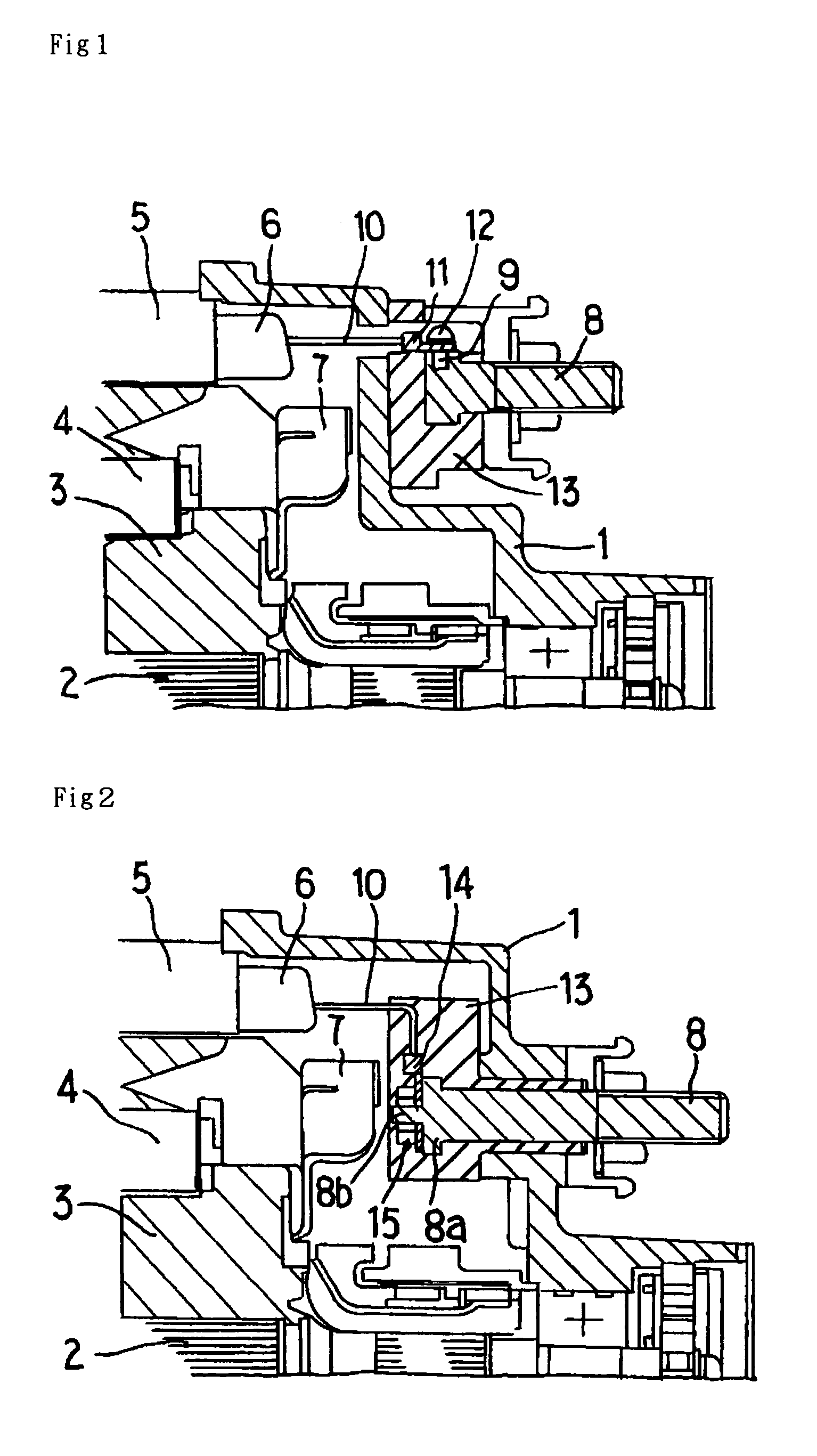
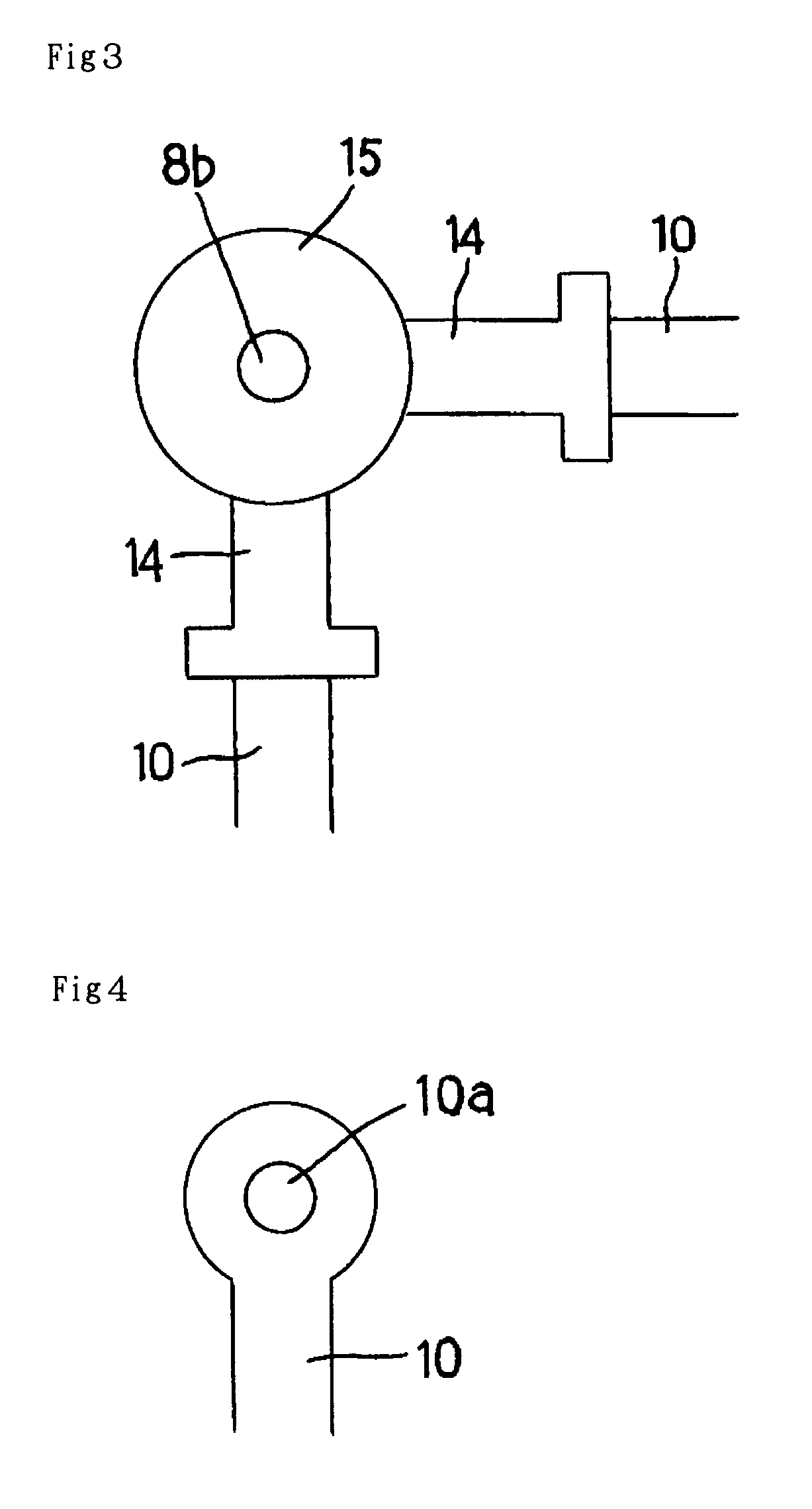
[0028]FIG. 2 is a partially sectional view showing an electric rotating machine according to Embodiment 2 of the invention. In this embodiment, a head portion 8a of a three-phase output terminal 8 is provided with a male screw 8b. A nut 15 connects at least one of the lead wires 10 of the stator winding 6 wound around the stator core 5 to the three-phase output terminal 8 through just a single metallic terminal 14.

[0029]In this manner, since a connection part between the lead wire 10 and the three-phase output terminal 8 is formed at the head portion 8a of the three-phase output terminal 8, the connection becomes easier.

[0030]Further, since the three-phase output terminal 8 and the metallic terminal 14 as well as the lead wire 10 of the stator winding 6 wound around the stator core 5 are fixed with the nut 15, strength of the three-phase output terminal 8 is sufficiently secured.

[0031]Furthermore, since the connection part between the lead wire 10 and the three-phase output terminal...

embodiment 3

[0033]This embodiment is the same as the foregoing Embodiment 2 in the aspect that the head portion 8a of the three-phase output terminal 8 is provided with the male screw 8b. In this embodiment, however, at least one lead wire 10 of the stator winding 6 wound around the stator core 5 is directly connected with the three-phase output terminal 8 with a nut 15, thus the metallic terminal 14 being omitted.

[0034]FIG. 4 is a front view showing the lead wire 10. Top end portion of the lead wire 10 is crushed so as to be provided with a hole 10a, through which the male screw 8b on the head portion 8a side of the three-phase output terminal 8 is inserted.

[0035]Although a nut is employed for fixation in the above description, it is also preferable that a screw is employed for fixation.

[0036]As described above, since no metallic terminal is interposed between the lead wire 10 and the three-phase output terminal 8, not only cost and manufacturing processes but also resistance are reduced, even...


PUM


Abstract

Reductions in cost and manufacturing processes are achieved by interposing a single metallic terminal between a lead wire of a stator and a three-phase output terminal. A rotor 3 is fixed onto a rotating shaft 2 disposed rotatably in a housing 1, and a stator core 5 is disposed opposite to the rotor 3. A stator winding 6 is wound around the stator core 5 and a lead wire 10 of the stator winding 6 is connected to a head portion 8a of a three-phase output terminal 8 through a single metallic terminal by a screw 12.

Description

BACKGROUND OF THE INVENTION[0001]1. Field of the Invention[0002]The present invention relates to an electric rotating machine for vehicle and, more particularly, to improvement in connection of a stator winding thereof.[0003]2. Description of the Related Art[0004]FIG. 8 is a sectional view showing a conventional electric rotating machine for vehicle. In the drawing, numeral 21 designates a front bracket, numeral 22 designates a rear bracket and numeral 23 designates a rotor. The rotor 23 includes a rotating shaft 24, field cores 25a and 25b, a field winding 26, and cooling fans 27a and 27b. Both front bracket 21 and rear bracket 22 support the rotating shaft 24 through bearings 28a and 28b. The field cores 25a and 25b are of Randel-type and the field winding 26 is internally wound thereon.[0005]The field cores 25a and 25b are fitted into the rotating shaft 24 and rotate integrally with the rotating shaft 24. The cooling fans 27a and 27b are fixed onto sides of the field cores 25a an...

Claims


Application Information

Patent Timeline
Patent Type & Authority Patents(United States)
IPC IPC(8): H02K5/22H01R4/02H01R4/28H01R4/34
CPCH02K5/225H01R4/023H01R4/34H01R2201/10
Inventor ISODA, HITOSHIASAO, YOSHIHITO
Owner MITSUBISHI ELECTRIC CORP
Why Eureka
Try Eureka