Hybrid power flow controller and method

a technology of power flow controller and hybrid power, which is applied in the direction of position/direction control, reactive power adjustment/elimination/compensation, and electric variable regulation, etc., can solve the problems of complex circuits, large and complex transmission systems, and difficulty in controlling the flow of power between nodes in such complex circuits

Inactive Publication Date: 2005-11-08
BEBIC JOVAN +1
View PDF9 Cites 31 Cited by
  • Summary
  • Abstract
  • Description
  • Claims
  • Application Information

AI Technical Summary

Problems solved by technology

As a result, transmission systems are typically large and complex electrical circuits consisting of hundreds of generation / consumption nodes and thousands of transmission lines.
Controlling the flow of power between the nodes in such complex circuits is a challenging problem.
It is further complicated by the need to control the voltage at each node to within a small tolerance of a rated value.
As the operating life of mechanical switches is inversely proportional to the rate at which switching cycles are performed under load, control of transmission systems was limited to slow sequential reconfigurations designed to reach the desired steady state operating point for a given set of conditions.
Dynamic control was not possible, and consequently transients initiated by faults, line and generator outages, or by equipment malfunction, were dealt with by operating the system conservatively and by a practice of over-design.
This resulted in considerable underutilization of system capacity.
Although their ability to indirectly damp power system transients was recognized early on, traditional practices in system planning and operation dominated the industry throughout the 1970s, and the use of SVCs was limited largely to provide reactive power support.
A characteristic of the power industry is that the demand for power rises steadily, while system upgrades are implemented through large and costly projects.
Over the years, energy, environmental, right-of-way, and cost problems have delayed the construction of both generation facilities and new transmission lines, so better utilization of existing power systems has become imperative.
While the exchange of reactive power does not impose further limitations, drawing active power in steady state operation requires that the converter be equipped with an energy storage device, which, in most cases, is impractical.
The shortcoming of all current FACTS controllers is their considerable price.
Nonetheless, due to the need for two converters, the investment required for UPFC installation discourages widespread deployment.

Method used


Image

  • Hybrid power flow controller and method
  • Hybrid power flow controller and method
  • Hybrid power flow controller and method

Examples


Embodiment Construction

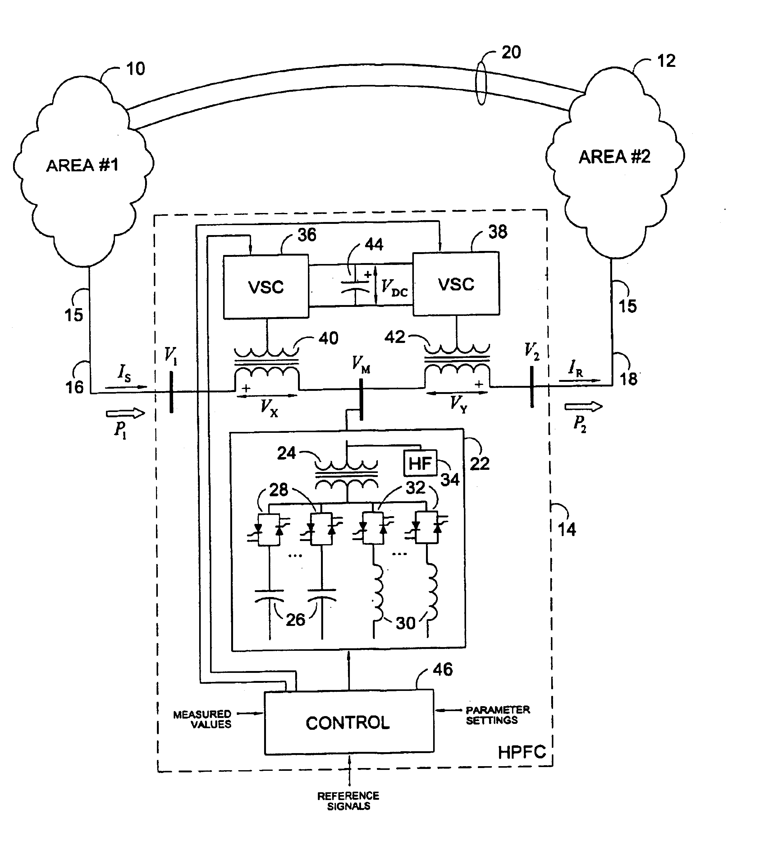
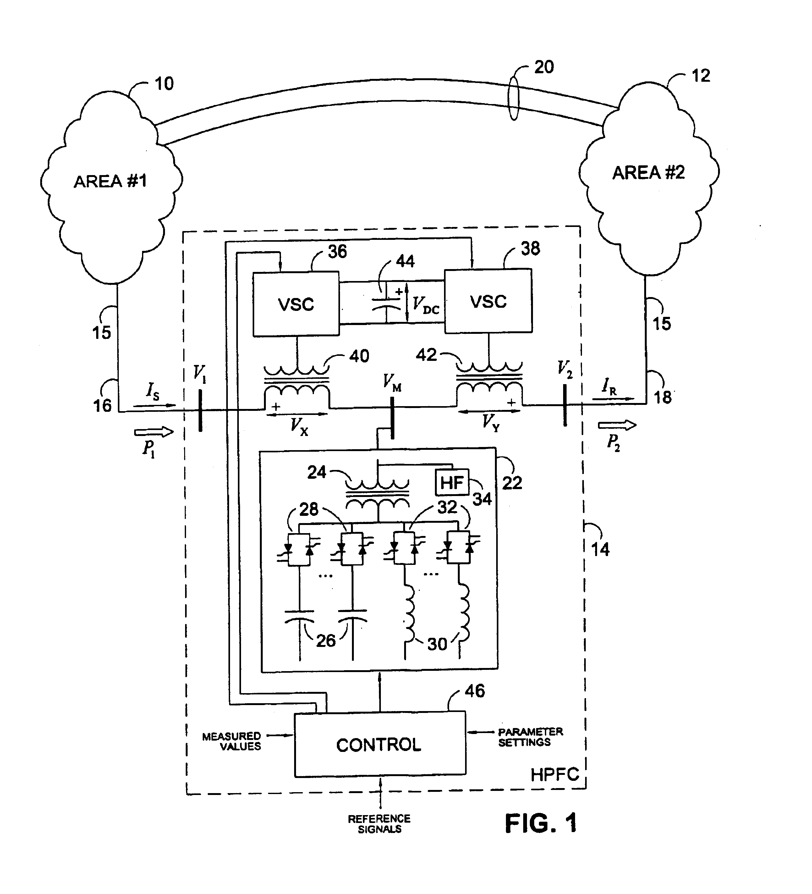
[0041]A single line diagram of an electrical power transmission system connecting two electrical regions 10 and 12, is illustrated in FIG. 1. A power flow controller 14, exemplary of an embodiment of the present invention, is installed on one transmission path 15 that connects region 10 with region 12. Each region 10 or 12 may be considered an area of electrical power production and / or power consumption. The transmission path 15 between regions 10 and 12 is thereby divided into two segments: segment 16 connecting area 10 to the power flow controller 14 and segment 18 connecting the power flow controller 14 to area 12. Other, parallel, transmission paths 20 may also exist between the areas 10 and 12.

[0042]Segments 16 and 18 are three-phase transmission lines carrying three phase alternating currents. The current flowing in the given phase of line segment 16 is denoted IS, and the current in the given phase of segment 18 is denoted IR. The line to neutral voltage at the point of conne...


PUM


Abstract

A power flow controller for controlling the flow of active and reactive power on an AC transmission line between an input and output includes first and second power converters, coupled to each other to exchange active power and coupled to the input and output. A controller is coupled to the power converters and controls the converters to provide a controlled quantity of active power to the output, and draw this controlled quantity of active power from the input of the power flow converter. Electric current is diverted at a node between the input and the output, allowing independent control of currents at the input and output. In a preferred embodiment, the two power converters are interconnected in series. A controllable susceptance is connected in shunt at a node between the converters to divert the current.

Description

CROSS-REFERENCE TO RELATED APPLICATION[0001]This application claims benefit from U.S. Provisional Application No. 60 / 423,374, filed Nov. 4, 2002, the contents of which are hereby incorporated by reference herein.FIELD OF THE INVENTION[0002]The present invention relates generally to the control of the flow of power in an alternating current (AC) transmission system. In particular, it relates to a power flow controller and a method for controlling the flow of active and reactive power on an AC transmission line.BACKGROUND OF THE INVENTION[0003]Typically, electrical energy is not produced where it is consumed, so it is necessary to transmit power from generation centres (large power plants) to load centres (cities or industrial facilities). High voltage transmission systems transport electrical energy from its source to the point of consumption.[0004]To ensure reliability of supply, and because of economic and other factors, it is common practice to interconnect transmission systems in...

Claims


Application Information

Patent Timeline
Patent Type & Authority Patents(United States)
IPC IPC(8): H02J3/18
CPCH02J3/1814H02J3/1842H02J3/1864Y02E40/12Y02E40/18Y02E40/22Y02E40/10Y02E40/20
Inventor BEBIC, JOVANLEHN, PETER
Owner BEBIC JOVAN
Why Eureka
Try Eureka