

Power supply apparatus
a technology of power supply and power supply device, which is applied in the direction of power conversion system, dc-dc conversion, instruments, etc., can solve the problems of large number of necessary components and difficulty in designing control circuits, and achieve high-speed response and highly practical configuration
- Summary
- Abstract
- Description
- Claims
- Application Information
AI Technical Summary
Benefits of technology
Problems solved by technology
Method used
Image

Examples
first embodiment
1. First Embodiment
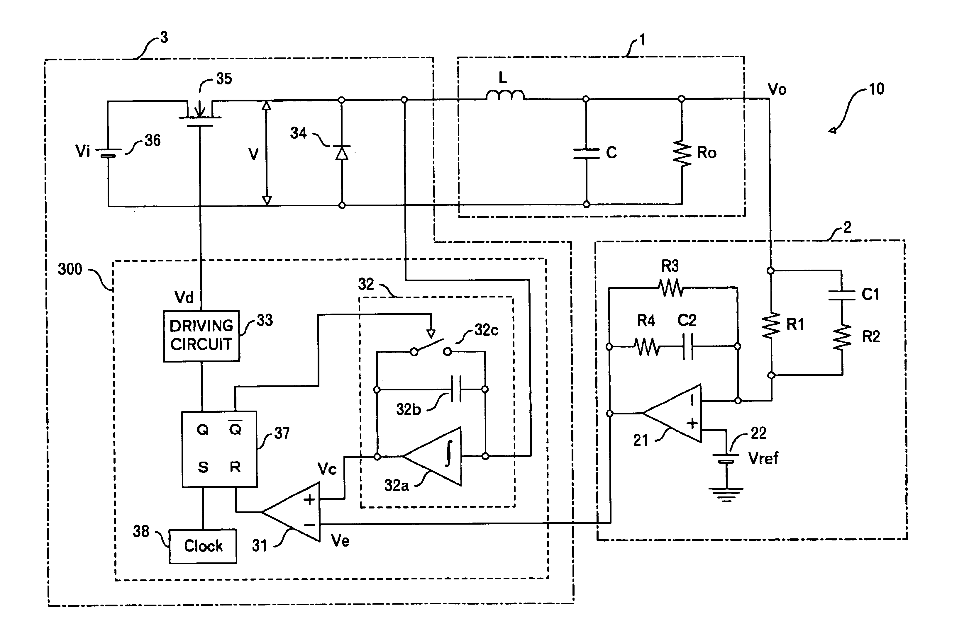
[0045]FIG. 5 shows a circuit configuration of a power supply apparatus 10 according to a first embodiment of the invention. The power supply apparatus 10 is a step-down type power supply apparatus, and is composed of an LC filter 1, a controller 2 as a PID controller, and a power converter 3 including a pulse controller 300.
[0046]The controller 2 includes resistors R1 to R4, capacitors C1 and C2, an amplifier 21 and a reference voltage power supply 22. The resistor R1 and the capacitor C1 are connected to a positive side terminal of a load Ro in the LC filter 1. That is, an output voltage Vo is inputted to this controller 2. The capacitor C1 and the resistor R2 are connected in series, and the capacitor C1 and the resistor R2 are connected in parallel to the resistor R1. Accordingly, the other end of the resistor R1 whose one end is connected to the capacitor C1 is connected to the resistor R2. Besides, the resistors R1 and R2 are connected to a negative side inpu...
second embodiment
2. Second Embodiment
[0068]FIG. 16 shows a circuit configuration of a power supply apparatus 20 of this embodiment. A difference from the power supply apparatus 10 shown in FIG. 5 is that a resistor Rc is connected in series to a capacitor C of an LC filter 1b, and circuit constants of resistors and capacitors of a controller 2b are changed as shown in FIG. 17. Accordingly, the connection relation will not be described here. Incidentally, the resistor Rc is called an equivalent series resistance and indicates a resistance component included in the capacitor C. Accordingly, Rc is approximately 2 mΩ. Although described later, the resistor Rc acts as phase-lead compensation in a high frequency range. The circuit constants of the resistors and the capacitors of the controller 2b are, as shown in FIG. 17, R1=1 KΩ, R2=60 Ω, R3=430 KΩ, R4=1.4 KΩ, C1=3.3 nF, and C2=1.8 nF.
[0069]When a transfer function of the controller 2b is calculated, an expression as indicated below is obtained. 24.65s2...
third embodiment
3. Third Embodiment
[0076]In the first and second embodiments, although the circuit constants are different from each other, the controller 2 and the controller 2b are equal to each other in the number of resistors and capacitors and the connection relation. In the third embodiment, a circuit as shown in FIG. 21 is adopted for a controller 2.
[0077]That is, the circuit is such that the resistor R3 in the controller 2 or the controller 2b shown in FIG. 5 is removed. More specifically, a controller 2c includes resistors R1, R2 and R4, capacitors C1 and C2, an amplifier 21, and a reference voltage power supply 22. The resistor R1 and the capacitor C1 are connected to the positive side terminal of the load Ro in the LC filter 1. The capacitor C1 and the resistor R2 are connected in series, and the capacitor C1 and the resistor R2 are connected in parallel to the resistor R1. Accordingly, the other end of the resistor R1 whose one end is connected to the capacitor C1 is connected to the re...
PUM
 Abstract
Description
Claims
Application Information