Various electrical characteristics and small test point testing module

a testing module and electrical characteristic technology, applied in the direction of electronic circuit testing, measurement devices, instruments, etc., can solve the problems of inability to raise the testing density, and inability to test high density testing, so as to achieve the effect of increasing the testing stability, reducing the cost of testing, and increasing the testing density

Inactive Publication Date: 2005-11-08
CHENG CHIN TSAI
View PDF4 Cites 7 Cited by
  • Summary
  • Abstract
  • Description
  • Claims
  • Application Information

AI Technical Summary

Benefits of technology

[0020]The primary objective of the invention herein is to provide a various electrical characteristics and small test point testing module in which the inner extremities of the linear probes are fixed at the clamp pin layer and the clamp pin layer is supported by second cushioning components and, therefore, the said linear probes are postured by an equal magnitude of elastic force against the tested object, thereby effectively increasing testing stability; at the same time, each linear probe does not have to equipped with an elastic component at their inner extremities, enabling testing apparatus component fabrication, assembly, and maintenance to be even simpler as well as more convenient, rapid, and economical.
[0021]Another objective of the invention herein is to provide a various electrical characteristics and small test point testing module in which afte...

Problems solved by technology

1. When the probe 2 contacts the tested object 3 test points 31, an elastic rebounding, compressive-decompressive force is required to prevent electrical damage to the test points 31 and, as a result, the needle body 24 relies on a spring 23 for withdrawal into the needle tube 22 such that the needle body 24 is automatically retracted elastically after compression and given such a structural arrangement, the entire probe 2 cannot be fabricated smaller or when fabricated smaller, the relative cost is very high, resulting in a cost increase and an inability to raise testing density.
2. Since the probe barrel 21 must be designed to match the dimensions of the probe 2, the dimensions are subject to limitations to the extent that the overall distribution density of the needle plate 12 needle holes 121 cannot be increased, resulting in an incapability to test high density testing point 31 tested objects 3.
3. Since the transferred signal of the tested object 3 testing point 31 results from the assembly and electrical contact of the needle body 24, the spring 23, the needle tube 22, and the probe barrel 21, poor and weak signal transmission results following numerous contacts and transfers that adversely affects testing quality, which become even more deteriorated when testing high density test points.
4. The probe 2 contacts the tested object 3 vertically and, as a result, the tip distance d of the adjacent probe 2 needle body 24 cannot be further reduced such that testing operations on tested objects 3 having small test points (i.e., test points 31 distributed at a high...

Method used


Image

  • Various electrical characteristics and small test point testing module
  • Various electrical characteristics and small test point testing module
  • Various electrical characteristics and small test point testing module

Examples


Embodiment Construction

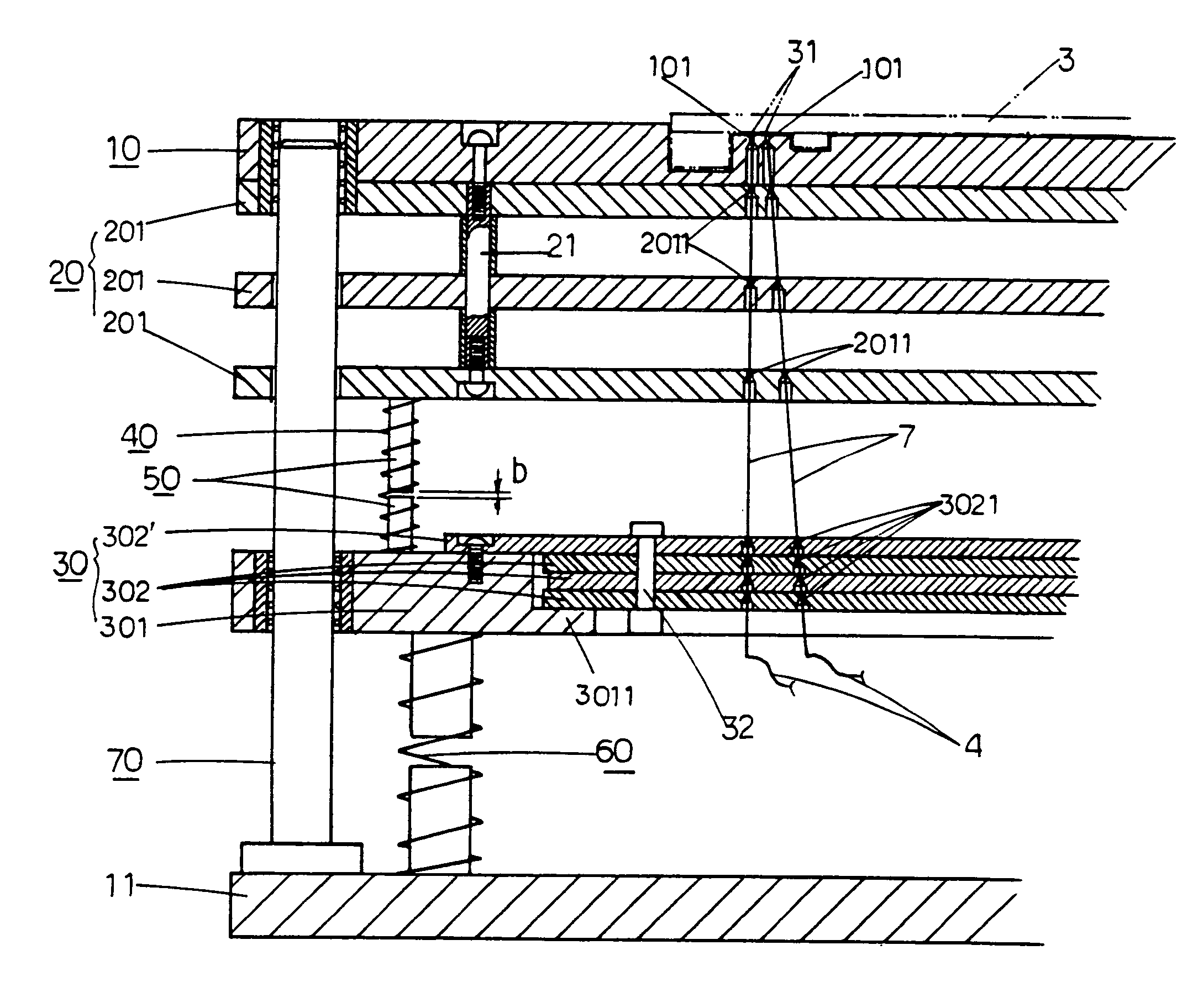
[0032]Referring to FIG. 5 and FIG. 6, the various electrical characteristics and small test point testing module of the invention herein is comprised of a carrier plate 10, a guide correction layer 20, a clamp pin layer 30, a linear probe 7, a first cushioning component 40, a travel adjustment rod 50, a second cushioning component 60, a guide post 70, and a base 11, wherein a said guide post 70 is installed at the four corners of the base 11 and the said carrier plate 10, guide correction layer 20, and clamp pin layer 30 are aligned by means of the guide posts 70 such that they are capable of vertical ascension and descension along the same axis.

[0033]The said carrier plate 10 is utilized to support and position a tested object 3 and has insertion holes 101 formed in it that are aligned with the test points 31 on the tested object 3 that provide for the pre-placement of linear probes 7.

[0034]The said guide correction layer 20 consists of a plurality of guide correction plates 201; e...


PUM


Abstract

A various electrical characteristics and small test point testing module comprised of a carrier plate, a guide correction layer, a clamp pin layer, linear probes, first cushioning components, second cushioning components, travel adjustment rods, guide posts, and a base, wherein the carrier plate, the guide correction layer, and the clamp pin layer are capable of vertical ascension and descension along the same axis by means of the guide posts. The linear probes are inserted into the carrier plate, the guide correction layer, and the clamp pin layer such that their inner extremities are fixed at the clamp pin layer and their outer extremities are situated at the carrier plate position. The first cushioning components and the travel adjustment rods are disposed between the guide correction layer and the clamp pin layer, while the second cushioning components are disposed between the base and the clamp pin layer such that the carrier plate, the guide correction layer, and clamp pin layer all are supported by an elastic force and each linear probe is subjected to an equal magnitude of elastic force.

Description

BACKGROUND OF THE INVENTION[0001]1) Field of the Invention[0002]The invention herein relates to a various electrical characteristics and small test point testing module, specifically a kind capable of testing the various electrical characteristics of a range of electronic products that provides for high testing density, even lighter testing pressure, and stabler testing results. Furthermore, the present invention can be utilized as a testing module for testing different blank circuit boards or component mounted boards.[0003]2) Description of the Prior Art[0004]The methods for conducting tests of conventional electronic product-use circuit boards typically includes the following examples:[0005]As indicated in FIG. 1 and FIG. 2, the prior art consists of an apparatus 1 base 11 having a needle plate 12, a clamp plate 13, a top plate 14, and a plurality of probes 2, wherein the said needle plate 12 needle holes 121 are aligned with the test points 31 of a tested object 3 (such as a prin...

Claims


Application Information

Patent Timeline
IPC IPC(8): G01R31/02G01R1/073
CPCG01R1/07328G01R1/07371G01R1/067
Inventor CHENG, CHIN-TSAI
Owner CHENG CHIN TSAI
Why Eureka
Try Eureka