Method and apparatus for compensating for media shift due to tape guide

a technology of tape guide and media shift, applied in the direction of track following, maintaining head carrier alignment, instruments, etc., can solve the problems of data loss, data loss, and data value often exceeding the value of the computer system,

Inactive Publication Date: 2005-11-08
IBM CORP
View PDF29 Cites 58 Cited by
  • Summary
  • Abstract
  • Description
  • Claims
  • Application Information

AI Technical Summary

Benefits of technology

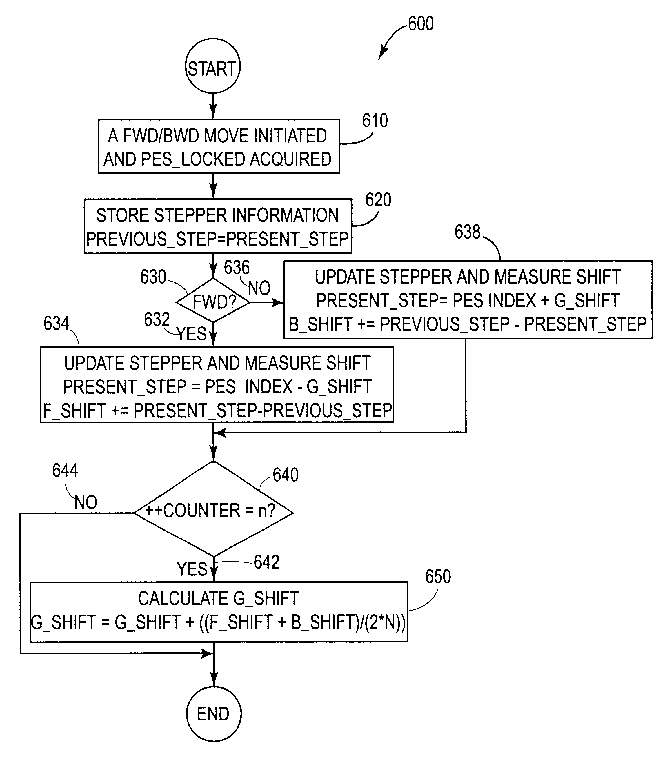
[0035]Another aspect of a tape servo system of the present invention is that the servo system updates the value representing a present position of the coarse actuator by determining whether the movement of the tape is forward or backward, defining the value representing a present position of the coarse actuator as the difference between a position error signal index and a groove shift value when the movement of the tape is forward and defining the value representing a present position of the coarse actuator as the sum of a position error signal index and a groove shift value when the movement of the tape is backward.

Problems solved by technology

As organizations' data warehouses grow, the threat of data loss carries a potentially larger fiscal price.
For example, the value of data often exceeds the value of the computer system within weeks of installation of the system.
Many factors can cause the loss of data including power brownout, power failure, human error, hard disk failure and other natural disasters.
In many cases, the lost data, if not properly backed-up, is simply not recoverable.
In other cases, data may still be re-assembled or re-captured from other system either electronically or manually, but both certainly involve a lot of cost and time.
Reliance solely on the track width and track separations to insure reliable read / write operations results in a significant waste of magnetic tape surface and thus limits the data density on the tape.
However, as the track width and the read / write head width narrow in an effort to increase the data capacity of a given tape area, any misalignment of the head with the track may lead to read / write repeatability failures and lost data.
Thus, the resolution of the head placement mechanism and the precision of the placement of the tape relative to the read / write head become limiting factors affecting the recording density of data on the magnetic tape surface in tape drives having static read / write heads.
The reels typically have runout causing the tape to move laterally as the tape is moved longitudinally.
As a result, the tape is very weak in the lateral direction, and can easily be damaged at the edge from the tape guide.
However, when wound on a reel, tape is typically subjected to stack shifts or stagger wraps, in which one wrap of the tape is substantially offset with respect to an adjacent wrap.
Other common sources of rapid lateral transient shifts include 1) a buckled tape edge in which the tape crawls against a tape guide flange and suddenly shifts laterally back down onto the bearing, 2) a damaged edge of the tape which causes the tape to jump laterally when contacting a tape guide, and 3) when the take up reel or supply reel runout is so significant that the reel flange hits the edge of the tape.
The occurrence of a lateral transient shift, however, is so rapid that neither the fine track follower nor the coarse track follower is able to respond, with the result that the tracking error becomes so large that writing must be stopped to prevent overwriting an adjacent track and to insure that the tracking error on read back is not so large as to cause a readback error.
However, this tends to stress and damage the edges of the tape, reducing its durability.
However, although the amplitude of the tape shift may be reduced somewhat by this approach, the speed of the shift is typically not reduced, and the track following servo error still occurs, reducing the performance of the tape drive.
Nevertheless, a problem is associated with a tape drive that uses a spiral grooved roller tape guide for controlling lateral tape motion transients in the tape path.
This biasing of tape results in relatively large lateral displacement between forward and backward direction and in the tape drive.
This movement could shift the tape servo format completely off of the servo head element resulting in loss of servo signal and ultimately failure in acquiring track lock.

Method used


Image

  • Method and apparatus for compensating for media shift due to tape guide
  • Method and apparatus for compensating for media shift due to tape guide
  • Method and apparatus for compensating for media shift due to tape guide

Examples


first embodiment

[0059]FIGS. 4A-D illustrates a tape roller bearing 400. The tape roller bearing 400 is rotatable about a central axis 471, for example, of a bearing shaft 472, parallel to the cylindrical peripheral surface 473, allowing the tape freedom of movement in the longitudinal direction.

[0060]The cylindrical peripheral surface comprises a frictional surface for contacting and engaging the surface of the tape and constraining movement of the tape in the lateral direction, for example peripheral surface 473, while not increasing friction in the longitudinal direction, thereby reducing the rate of the lateral transient movement of the tape to allow the track following servo system to follow the reduced rate lateral transient movement of the longitudinal tracks.

[0061]Thus, the tape is contacted and engaged at its surface rather than at an edge, limiting lateral slip and providing substantial lateral drag to the tape, while the tape rolls freely with the tape roller bearing as the tape roller be...

second embodiment

[0063]FIG. 5 illustrates a tape roller bearing 500. In FIG. 5, the flanges are removed, and the smooth cylindrical surfaces 577 and 578 extend to the edges of the tape roller bearing 500. In this embodiment, any excessive amplitude lateral movement could be prevented by conventional tape guiding at adjacent locations.

[0064]In the embodiments of FIG. 5, the tape roller bearing frictional cylindrical peripheral surface 573 comprises a plurality of lands 575 separated by grooves 576. The lands extend about the cylindrical peripheral surface 573 in a circumferential direction generally parallel to the longitudinal direction that the tape is moved. Any potential air bearing that could form between the surface of the tape and the surface of the roller bearing, e.g., due to the air drawn along by the tape as it is moved rapidly, is collapsed to provide contact between the tape surface and the lands 575 for engaging the surface of the tape. The lands 575 and grooves 576 extend in the circum...


PUM

PropertyMeasurementUnit
timeaaaaaaaaaa
widthaaaaaaaaaa
densityaaaaaaaaaa

Abstract

A method and apparatus for compensating for media shift due to spiral groove roller tape guide is disclosed. The lateral tape shift is measured. Then the control of the coarse actuator is adjusted for the lateral tape shift so that the movement of the coarse actuator follows the tape shift.

Description

BACKGROUND OF THE INVENTION[0001]1. Field of the Invention[0002]This invention relates in general to track following servo control for data storage systems, and more particularly to a method and apparatus for compensating for lateral media shift resulting in forward to backward offset in tape guiding.[0003]2. Description of Related Art[0004]Due to the Internet and the globalization of manufacturing and service-oriented industries, businesses are collecting and analyzing data at an ever increasing rate. As organizations' data warehouses grow, the threat of data loss carries a potentially larger fiscal price. For example, the value of data often exceeds the value of the computer system within weeks of installation of the system. Many factors can cause the loss of data including power brownout, power failure, human error, hard disk failure and other natural disasters. In many cases, the lost data, if not properly backed-up, is simply not recoverable. In other cases, data may still be r...

Claims


Application Information

Patent Timeline
Patent Type & Authority Patents(United States)
IPC IPC(8): G11B5/584
CPCG11B5/584
Inventor BUI, NHAN X.KOSKI, JOHN ALEXANDERSASAKI, AKIMITSUTSURUTA, KAZUHIRO
Owner IBM CORP
Why Eureka
Try Eureka