Apparatus for dividing bank in flash memory

Inactive Publication Date: 2005-11-08
SK HYNIX INC
View PDF2 Cites 19 Cited by
  • Summary
  • Abstract
  • Description
  • Claims
  • Application Information

AI Technical Summary

Benefits of technology

[0007]The present invention is contrived to solve the aforementioned problems. The present invention is directed to provide an apparatus for dividing a bank in a flash memory in which a block of the flash memory is divided into two banks and respective page

Problems solved by technology

This type of the flash memory, however, requires long time to read a first data and also needs long time for programming.
Furthermore, the conventional flash memory has a disadvantage that it could not perform

Method used


Image

  • Apparatus for dividing bank in flash memory
  • Apparatus for dividing bank in flash memory
  • Apparatus for dividing bank in flash memory

Examples


Example

[0017]The present invention will now be described in detail in connection with preferred embodiments with reference to the accompanying drawings, in which like reference numerals are used to identify the same or similar parts.

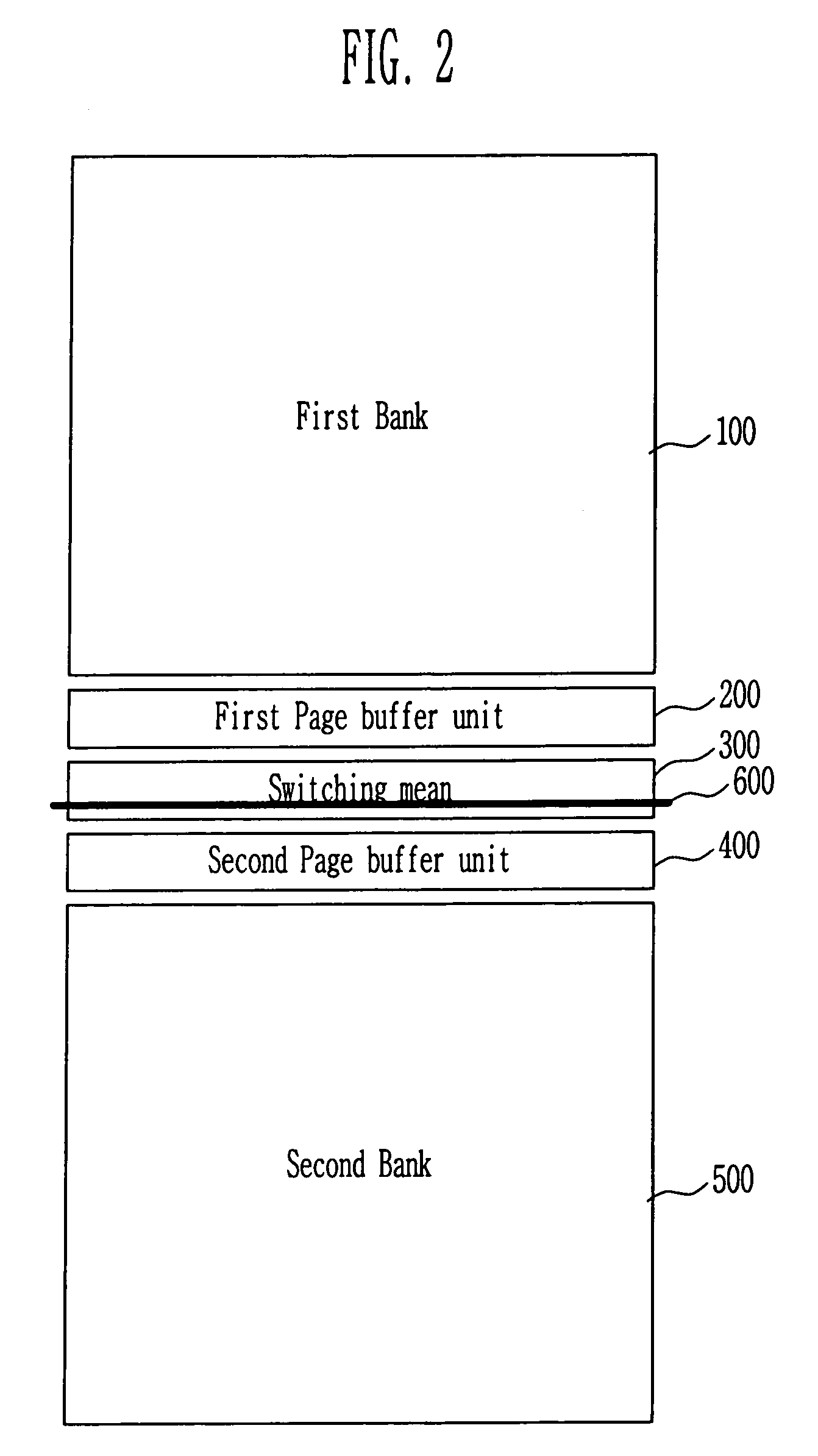
[0018]FIG. 2 is a conceptual view illustrating the structure of a bank in a NAND flash memory according to a preferred embodiment of the present invention.

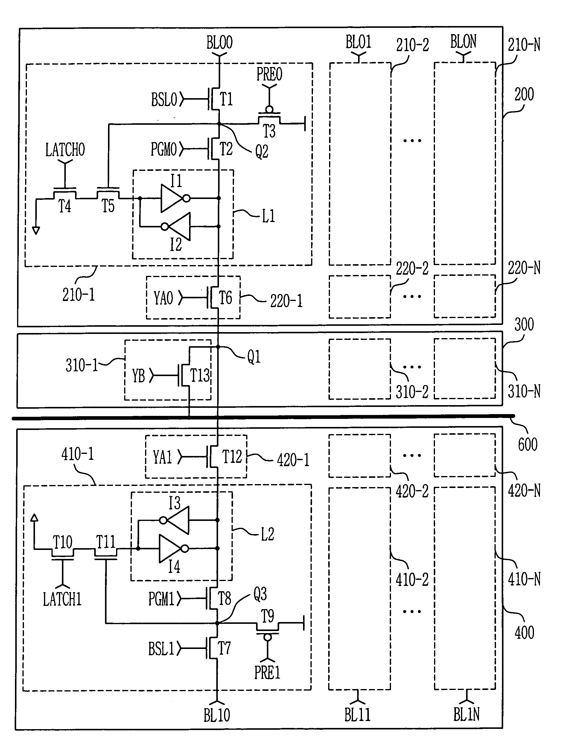
[0019]Referring to FIG. 2, proposed chip architecture has an entire memory cell array divided into a first bank 100 and a second bank 500. The first bank 100 and the second bank 500 include a first page buffer unit 200 for paging the first bank 100 and a second page buffer unit 400 for paging the second bank 500, respectively. The first page buffer unit 200 and the second page buffer unit 400 share the same input / output line 600 through a switching mean 300.

[0020]The first page buffer unit 200 and the second page buffer unit 400 can exchange data each other, which allows a counterpart to be used as a cache bu...


PUM


Abstract

The present invention relates to an apparatus for dividing a bank in a flash memory. A block of the flash memory is divided into two banks and each page buffer is located between the two banks to share an input/output line. Therefore, it is possible to shorten the length of a bit line, improve a data sensing rate, and allow one bank to perform one operation while the other bank performs a read, write or erase operation.

Description

BACKGROUND[0001]1. Field of the Invention[0002]The present invention relates to an apparatus for dividing a bank in a flash memory and, more particularly, to an apparatus for dividing a bank in a NAND flash.[0003]2. Discussion of Related Art[0004]A conventional NAND flash memory can be implemented with a very small cell area and is thus suitable for high-integrated memory devices. This type of the flash memory, however, requires long time to read a first data and also needs long time for programming. Furthermore, the conventional flash memory has a disadvantage that it could not perform one operation while the other operation is performed.[0005]FIG. 1 is a conceptual view illustrating the structure of a bank in a conventional NAND flash memory.[0006]Referring to FIG. 1, a page buffer 20 and a cache buffer 30 are intervened between a NAND flash memory bank 10 and an input / output line 40. Data inputted via the cache buffer 30 are sent to the page buffer 20. Data for performing a next ...

Claims


Application Information

Patent Timeline
IPC IPC(8): G11C16/06G11C16/10G11C16/26G11C16/02G11C16/00
CPCG11C16/10G11C16/26G11C2216/22G11C16/00
Inventor PARK, JIN SU
Owner SK HYNIX INC
Why Eureka
Try Eureka