
Electronic apparatus for a bus system

a bus system and electronic equipment technology, applied in the direction of automatic controllers, programme control, instruments, etc., can solve the problems of complex configuration software, inability to communicate between the configuration software and the device, and the device is unable to operate normally, so as to reduce the effort for the use of the device in different areas of application, simplify the configuration of the device, and avoid the effect of affecting the operation speed

Active Publication Date: 2005-11-08
SICK AG
View PDF28 Cites 23 Cited by
  • Summary
  • Abstract
  • Description
  • Claims
  • Application Information

AI Technical Summary

Benefits of technology

[0010]It is an object of the present invention to provide a cost-favorable and flexible solution with which different electronic apparatuses of the initially named kind, such as sensors, actuators and controls, can be connected to the most varied bus systems. The effort for the use of the devices in different areas of application should also be reduced and the configuration of the devices simplified. At the same time, defective parameterizations of the devices should be reliably recognizable.
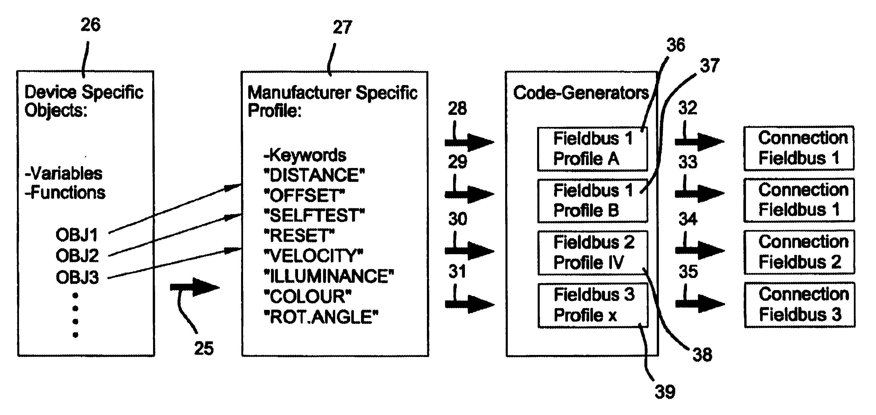
[0019]The quantity of the mappings required in total is greatly limited by this decoupling of the manufacturer-specific device protocol and the application-specific device protocol. Without such a decoupling, the use of n devices in m application fields requires n*m mappings of the device parameters onto the respective application profile. With the decoupling in accordance with the invention, the number of combinational possibilities reduces to only n+m individual mappings. Each device must be adapted only once using the decoupling in accordance with the invention as the basis—independently of the desired application—namely to the manufacturer-specific profile. Furthermore, precisely one mapping of the manufacturer-specific profile onto the respective application profile is prepared for each application field which can then be used for all devices. By the inclusion of the manufacturer-specific profile as an additional description plane, there is thus a decoupling of the device and of the application field and thus a reduction in the development costs.
[0025]In accordance with a further advantageous embodiment of the invention, the universal definition engine is formed by one or more files. These files can be present, for example, in XML format. The XML format is advantageous since it defines a formal standard which allows the further processing of the information contained in the universal definition engine with a plurality of tools. Furthermore, XML has the advantage that the information can be stored distributed physically in a plurality of files and that nevertheless a total view as one single document is maintained. Generally, any other format is also suitable which satisfies the formal requirements. The two main components of the universal definition engine are formed by the description of the communication and of the visualization. The format is, however, open and can thus be expanded by further components as required.
[0026]In accordance with a further preferred embodiment of the invention, the device-specific definition engine is provided inside the electronic apparatus. In this manner, a very simple addressing of the parameter information is possible, for example starting from another apparatus connected to the data bus or from the configuration program. However, this solution has the disadvantage that relatively high demands are made on the memory requirements inside the device.

Problems solved by technology

A further problem lies in the fact that the allocation of parameters and functions to specific variables, addresses or channels is usually carried out in so-called profiles (device profiles) with different fieldbuses.
If this description is not present, communication between the configuration software and the device is not possible.
A further problem area lies in the fact that numerous dependencies between the device parameters have to be taken into account on the parameterization (configuration) of field devices.
A parameter set accepted by the configuration software as permitted in the development phase can thus result in a standstill of the device or in another error in operation.
Furthermore, the double provision of the corresponding software parts inside the device and inside the configuration software is complex and causes additional costs.

Method used


Image

  • Electronic apparatus for a bus system
  • Electronic apparatus for a bus system
  • Electronic apparatus for a bus system

Examples


Embodiment Construction

[0037]The following description of the preferred embodiment(s) is merely exemplary in nature and is in no way intended to limit the invention, its application, or uses.

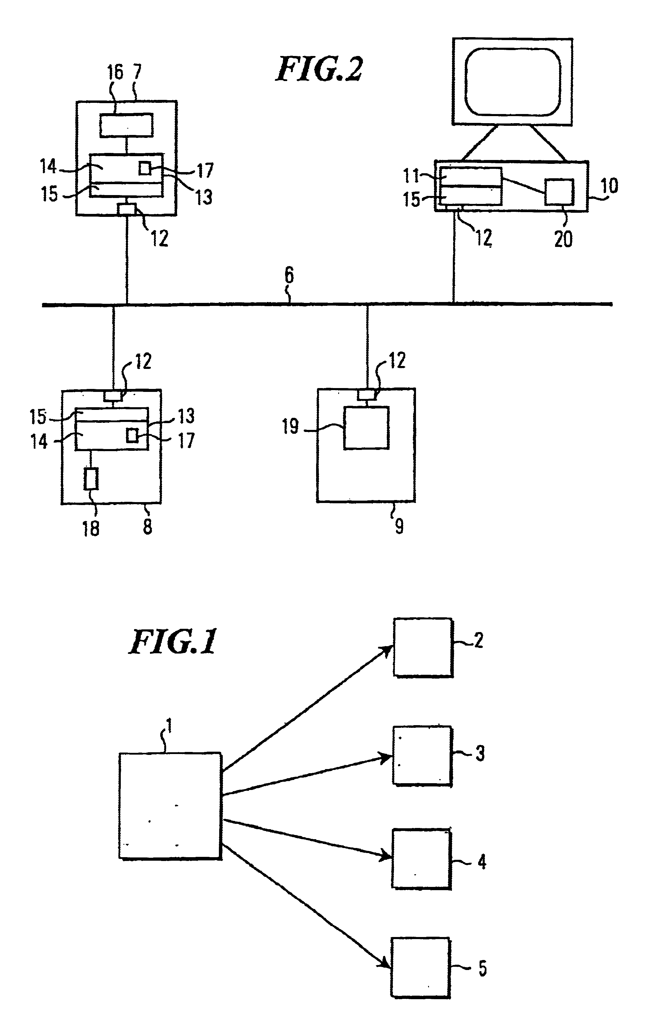
[0038]FIG. 1 shows a universal definition engine 1 (universal device description) which is stored, for example, as an XML file and in which all facets and information of an electronic apparatus forming a sensor, an actuator or a control are stored in a fixedly pre-determined format. Important elements are, for example, a communication interface description as well as a visualization interface description for a configuration program of the electronic apparatus.

[0039]In accordance with the invention, a plurality of different device-specific elements can be generated from the universal definition engine, for example a documentation 2 (in a text format or in a word processor format). This documentation can be printed out or read on a computer and is automatically always complete and always at the latest device status.

[004...


PUM


Abstract

An electronic apparatus forming a sensor, an actuator or a control is described comprising a control engine and an integrated bus interface. The apparatus can be connected via the bus interface to a data bus for the communication of the apparatus with at least one further apparatus forming a sensor, an actuator or a control and connected to the data bus. Furthermore, the apparatus includes a device-specific definition engine in which parameters required for the communication, function and / or configuration of the electronic apparatus are stored, with the device-specific definition engine being present in a device-specific format and the parameters being able to be accessed via the control engine. In accordance with the invention, a universal definition engine is provided which is present in a device-independent, standardized format and in which all the parameters of the electronic apparatus required for the communication, function and configuration and additional parameters characterizing the electronic apparatus are stored. Furthermore, the device-specific definition engine can be generated automatically from the universal definition engine.

Description

CROSS-REFERENCE TO RELATED APPLICATIONS[0001]This application claims priority to German Patent Application No. 102 43 781.5 filed Sep. 20, 2002, which application is herein expressly incorporated by reference.BACKGROUND OF THE INVENTION[0002]The present invention relates to an electronic apparatus forming a sensor, an actuator or a control and comprising a control engine as well as an integrated bus interface via which the apparatus can be connected to a data bus for the communication of the apparatus with at least one further apparatus forming a sensor, an actuator or a control and connected to the data bus and comprising a device-specific definition engine in which parameters required for the communication and / or configuration of the electronic apparatus are stored, with the device-specific definition engine being present in a device-specific format and the parameters being able to be accessed via the control engine.[0003]In many areas of application of automation technology, diff...

Claims


Application Information

Patent Timeline
IPC IPC(8): G05B19/042G05B19/04
CPCG05B19/0426G05B2219/25061G05B2219/25428G05B2219/31121G05B2219/31161
Inventor FEHRER, DETLEFHEIDEPRIEM, SEBASTIANSTADLER, EDGARVOLLMER, URS
Owner SICK AG
Learn More