Network restoration using refreshed switch state tables

a switch state and switch technology, applied in the field of network restoration, can solve the problems of optical fiber and optical equipment damage, optical network failures or faults, and various damage through a variety, and achieve optimal restoration, less unrestored traffic, and more accurate switch state tables

Inactive Publication Date: 2005-11-08
CIENA
View PDF25 Cites 17 Cited by
  • Summary
  • Abstract
  • Description
  • Claims
  • Application Information

AI Technical Summary

Benefits of technology

[0016]Yet another technical advantage of the present invention includes the capability to refresh the various switch state tables that are locally accessible by the various OCCSs by continuing to run simulations, either at a central database or through off-line DRA simulations and on-line DRA simulations, such as those described in U.S. patent application Ser. No. 09 / 148,943, filed Sep. 8, 1998, and now U.S. Pat. No. 6,404,733, and entitled Method of Exercising A Distributed Restoration Process in an Operational Telecommunications Network, which is hereby incorporated by reference for all purposes. This results in more accurate switch state tables.
[0017]The present invention provides the significant technical advantage that includes the capability to take into account the “new” optical network configuration after a failure has occurred, or when any network reconfiguration or provisioning occurs. Thus, subsequent switch state tables will take into account this configuration when calculated and refreshed in the future. This results in a more optimal restoration with less unrestored traffic.
[0018]Other technical advantages are readily apparent to one skilled in the art from the following figures, description, and claims.

Problems solved by technology

Optical network failures or faults may be caused by any number of events or reasons, including damaged or severed optical fibers, or equipment failure.
Because optical fibers may be installed virtually anywhere, including underground, above ground or underwater, they are subject to damage through a variety of ways and phenomena.
Optical fibers and optical equipment may be damaged or severed, for example, by lightning, fire, natural disasters, traffic accidents, digging, construction accidents, and the like.
Because optical fibers carry far greater amounts of information than conventional copper wires used to transmit electrical telecommunications signals, the loss of an optical fiber can cause far more user disruptions when compared with the loss of a copper wire.
Because dozens of fibers may be routed within a single cable or conduit, a damaged or severed cable or conduit will potentially result in far greater user disruptions and outages than the loss of a cable or conduit of copper wires.
Because of the large amount of data or bandwidth an optical network carries, the amount of time it takes to identify the location of an optical network failure, and the time it takes then to reconfigure the optical network, significant amounts of telecommunications traffic are often lost.
Further, the reconfiguration of an optical network may result in the loss of other telecommunications traffic if not done efficiently or optimally.
The capability to detect failures in an optical network is generally considered more difficult than detecting a failure in a telecommunications network that operates in the electrical domain.
This failure detection difficulty normally results in increased time to locate a network failure, which further complicates the capability to efficiently restore a failure in an optical network.
Prolonged outages result in decreased network revenues, business losses by commercial users, and an overall reduction in user confidence and satisfaction.
For example, the loss of a single optical link, such as an optical link carrying a Wavelength Division Multiplexed (“WDM”) signal, may result in the loss of hundreds of thousands of phone calls and computer data transmissions.
Prior restoration techniques and methodologies were generally designed for restoring telecommunications networks operating in the electrical domain as opposed to the optical domain, which presents additional challenges.
Unfortunately, each of these techniques suffer from significant problems and disadvantages.
The central control and dispatch model suffers from a serious speed disadvantage because of the time it takes to detect failures, communicate failures to the central control, to calculate an acceptable solution, and then to communicate back to each node a desired switch configuration.
Often, the central control approach is inaccurate because the most recent model of the network is not used.
This approach is not acceptable in most optical networks, especially WDM optical networks.
This solution still may suffer significant disadvantages, such as excessive time to contact each such OCCS with the needed provision information and the results may be based on bad or inaccurate network model information.
Unfortunately, for optical networks, this technique of messaging before the link is restored takes too long.
Response times as short as 100 to 200 milliseconds may result in dropped traffic.
Another disadvantage is that the various nodes may get into a loop condition where the nodes are contending against one another for network resources.

Method used


Image

  • Network restoration using refreshed switch state tables
  • Network restoration using refreshed switch state tables
  • Network restoration using refreshed switch state tables

Examples


Embodiment Construction

[0025]It should be understood at the outset that although an exemplary implementation of the present invention is illustrated below, the present invention may be implemented using any number of techniques, whether currently known or in existence. The present invention should in no way be limited to the exemplary implementations, drawings, and techniques illustrated below, including the exemplary design and implementation illustrated and described herein.

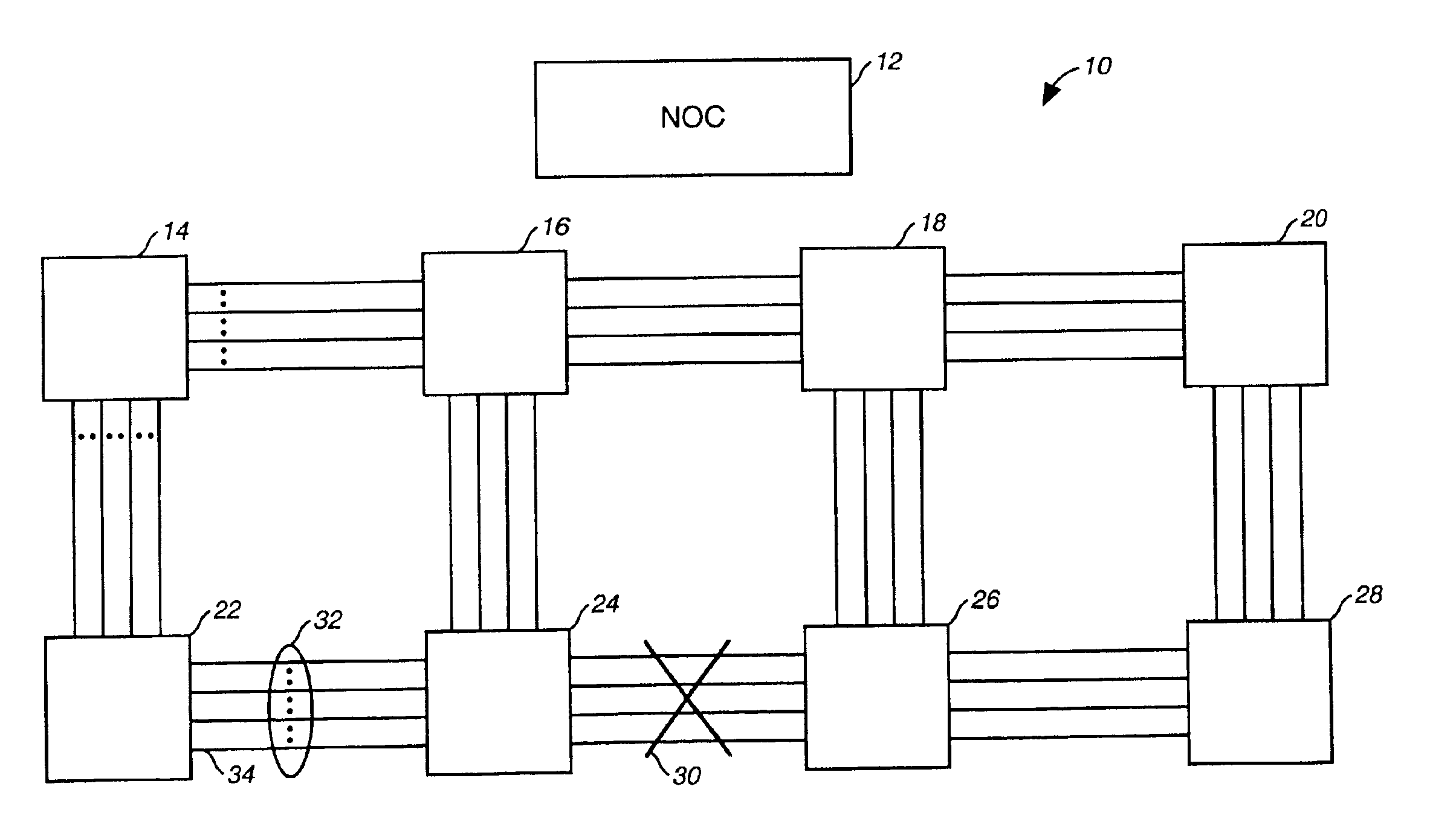
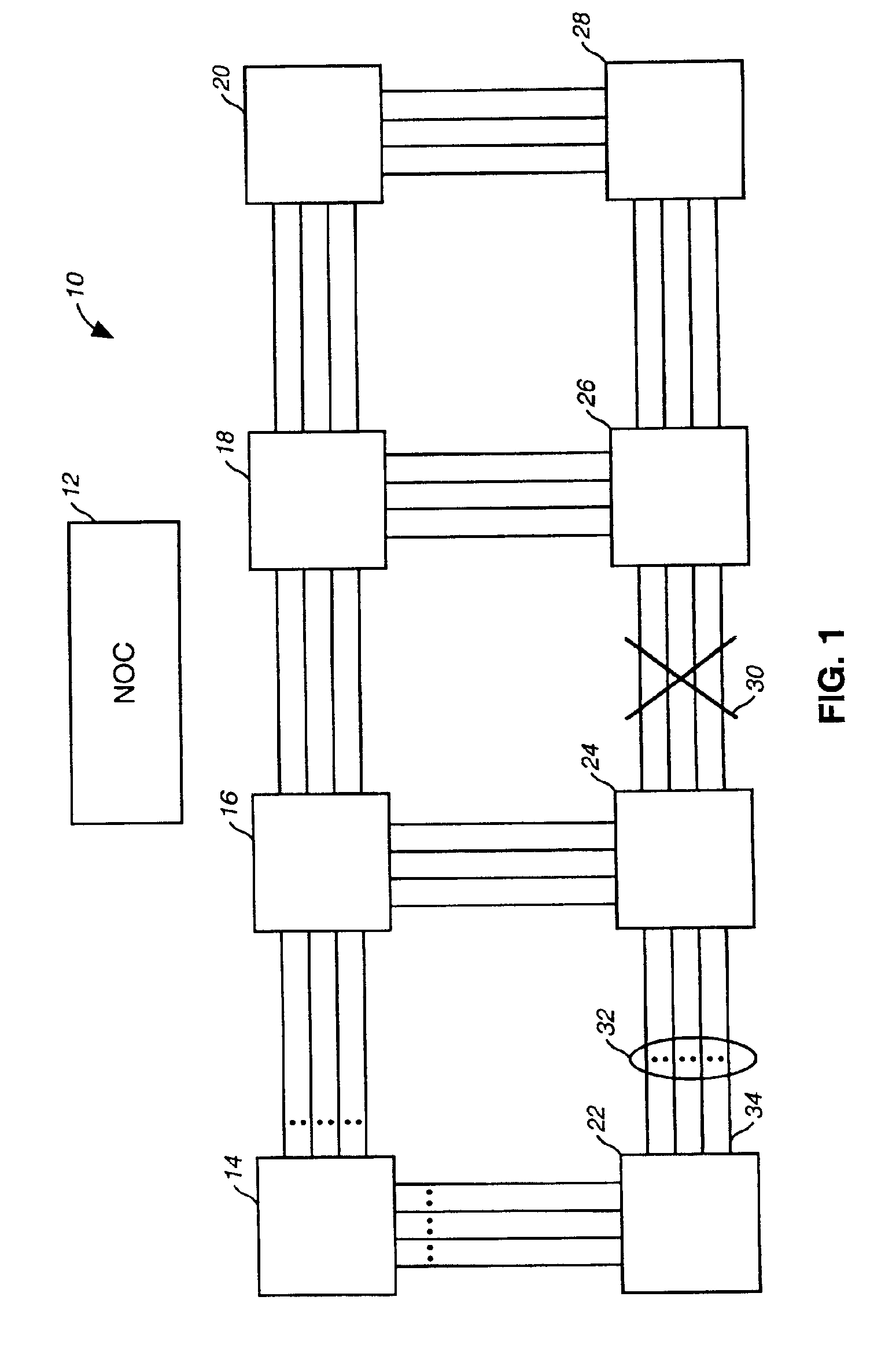
[0026]FIG. 1 is a block diagram that illustrates an optical network 10 that includes a plurality of Optical Cross Connect Switches (“OCCSs”) or nodes coupled in a mesh configuration through various fiber optic links, and a Network Operations Center (“NOC”) 12 in communication with the plurality of OCCSs or nodes of the optical network 10. The optical network 10 is provided in a mesh configuration (but could be provided in other network topologies) that includes an OCCS 14, an OCCS 16, an OCCS 18, an OCCS 20, an OCCS 22, an OCCS 24, a...


PUM


Abstract

An exemplary method and optical network that provide optical network restoration using refreshed state tables are disclosed. The exemplary method for recovering from a failure in an optical network using refreshed switch state tables includes generating and storing connection information in switch state tables of associated optical switches that define optical link connections to be made in the event of a failure, monitoring whether a failure has occurred, and refreshing the switch state tables by continuing to generate and store connection information in the plurality of switch state tables that are associated with the plurality of optical switches of the optical network until the failure in the optical network is detected. Once the failure is detected, optical switching is automatically performed in the optical switches based on the lookup table connection information in the switch state tables that are associated with the optical switches. The exemplary method may then include determining whether any of the telecommunications traffic in the optical links of the optical network was not restored due to the optical switching that was automatically performed.

Description

TECHNICAL FIELD OF THE INVENTION[0001]This invention relates in general to the field of network restoration and more particularly to network restoration using refreshed switch state tables.BACKGROUND OF THE INVENTION[0002]Optical networks include various optical switches or nodes coupled through a network of optical fiber links. Optical network failures or faults may be caused by any number of events or reasons, including damaged or severed optical fibers, or equipment failure. Because optical fibers may be installed virtually anywhere, including underground, above ground or underwater, they are subject to damage through a variety of ways and phenomena. Optical fibers and optical equipment may be damaged or severed, for example, by lightning, fire, natural disasters, traffic accidents, digging, construction accidents, and the like.[0003]Because optical fibers carry far greater amounts of information than conventional copper wires used to transmit electrical telecommunications signal...

Claims


Application Information

Patent Timeline
Patent Type & Authority Patents(United States)
IPC IPC(8): H04L1/22
CPCH04L1/22
Inventor FEE, JOHN A.
Owner CIENA
Why Eureka
Try Eureka