Detection of rolling contact fatigue

a technology of rolling contact and fatigue, applied in the direction of instruments, using mechanical means, material magnetic variables, etc., can solve the problems of cracks, wheels or rails of railways, and stresses in structures such as rails, and achieve the effect of enhancing sensitivity to the onset of rolling contact fatigue and accurate determination of stress levels

Inactive Publication Date: 2005-11-15
BAKER HUGHES ENERGY TECH UK LTD
View PDF20 Cites 12 Cited by
  • Summary
  • Abstract
  • Description
  • Claims
  • Application Information

AI Technical Summary

Benefits of technology

[0008]Surprisingly this simple mapping has been found to give an accurate representation of the variation of the signals with material property, in particular stress, and provides a simple way to distinguish these variations from variations arising from lift-off or other geometrical variations, which in the context of bearings, rollers, wheels or rails will typically arise as a result of curvature of the surface.
[0010]The probe, or at least some of the probes, may also include a second magnetic sensor between the two poles and arranged to sense magnetic flux density perpendicular to the direction of the free space magnetic field between the poles. This second sensor would detect no signal if the material were exactly isotropic; however stress induces anisotropy into the magnetic properties of the material, and so the signals received by the second sensor (or flux-rotation sensor) are a measure of this stress-induced magnetic anisotropy. The variations in the flux rotation signals at different probe orientations, at a location on the object, enable the directions of the principal stress axes to be accurately determined. The flux rotation signals can also be related to the stress.
[0014]Generally, the more different probe orientations are used for taking measurements the more accurate the determination of stress levels and principal axes can be, and so the sensitivity to the onset of rolling contact fatigue will be enhanced. The directions of the principal axes may be ascertained from flux-linkage, flux-leakage, or flux rotation signals: the signal maxima and minimafor flux-linkage and flux-leakage would be expected to be along these directions, whereas those for flux-rotation would be along the bisection angles between these directions. If the surface is curved, the flux-rotation signal response will however be modified by the curvature.

Problems solved by technology

Where there is rolling contact between objects under a load, there may be the development of cracks.
This may be a problem in bearings, and in the wheels or rails of railways.
The stresses in structures such as rails arise from various causes including changes of temperature, and the loads and pressures due to use.

Method used


Image

  • Detection of rolling contact fatigue
  • Detection of rolling contact fatigue
  • Detection of rolling contact fatigue

Examples


Embodiment Construction

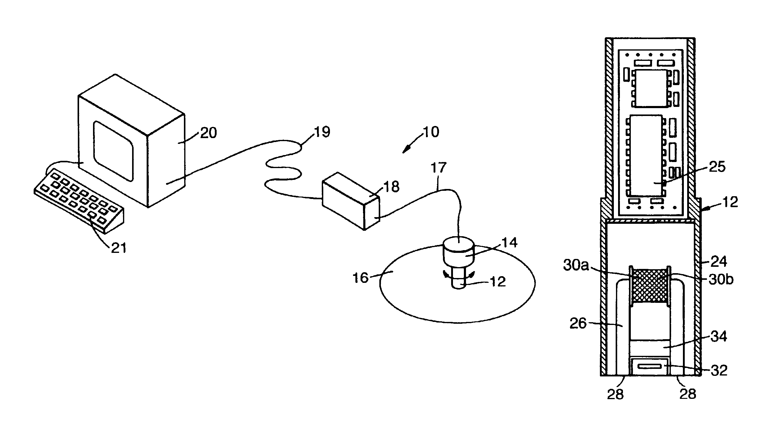
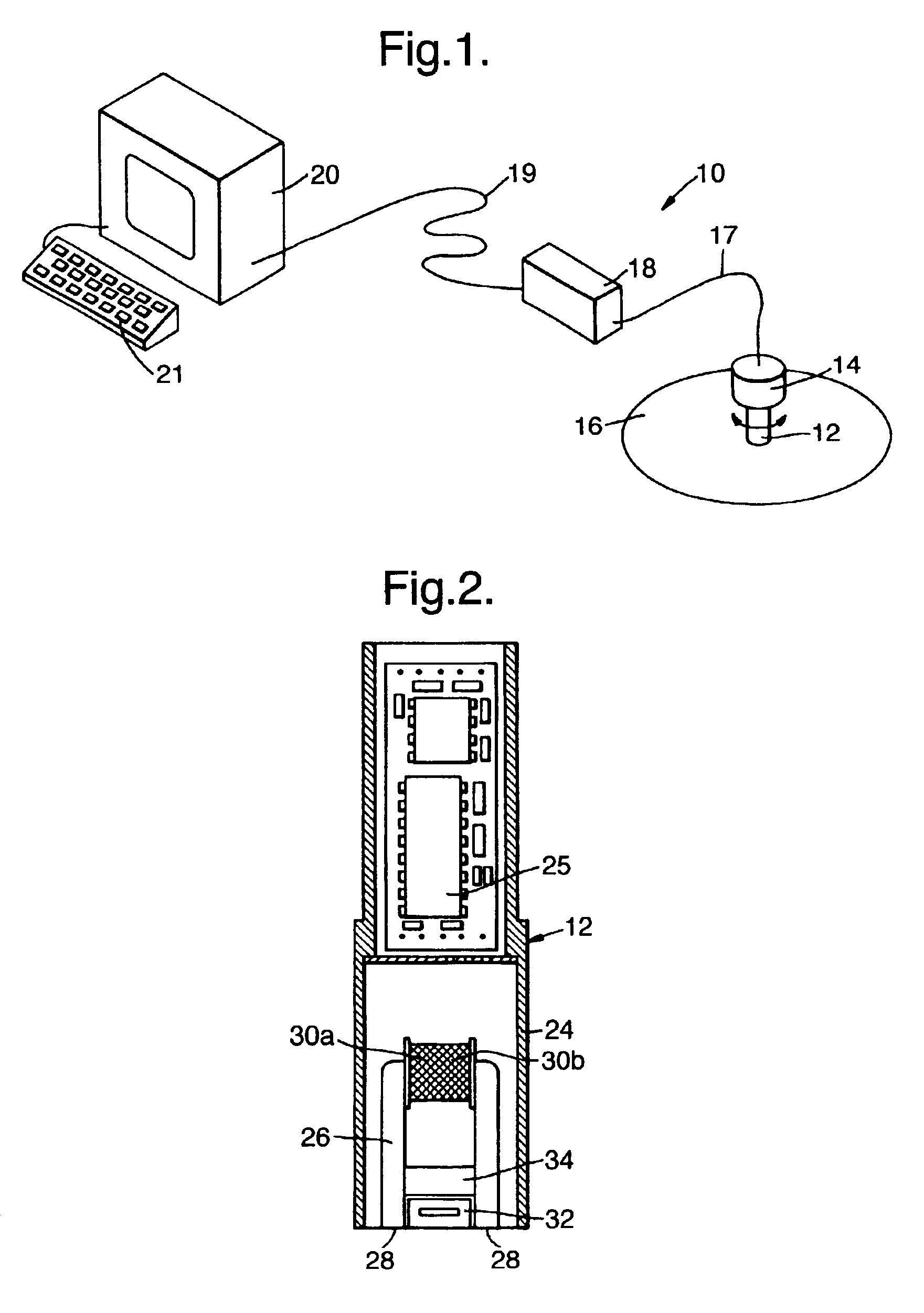
[0021]The invention will be described with reference to an apparatus suitable for measuring the stresses in a ferromagnetic object, such as a rail. Referring to FIG. 1, a stress measuring apparatus 10 includes a sensor probe 12 comprising sensors for flux-linkage, flux-rotation and flux-leakage, the probe 12 being attached to an electric motor 14 which can be held by an operator, so the motor 14 can turn the probe 12 with one end adjacent to a surface of a steel object 16 in which the stress is to be determined. The sensor probe 12 and motor 14 are connected by a 2 m long umbilical cable 17 to a signal conditioning / probe driver unit 18. The unit 18 is connected by a long umbilical cable 19 (which may for example be up to 300 m long) to an interface unit within a microcomputer 20, which has a keyboard 21. Operation of the apparatus 10 is controlled by software in the microcomputer 20.

[0022]The interface unit within the microcomputer 20 generates sine and cosine functions at an angula...


PUM

PropertyMeasurementUnit
depthaaaaaaaaaa
alternating frequenciesaaaaaaaaaa

Abstract

The onset of rolling contact fatigue in an object may be detected by measuring the residual stresses in the surface of the object, and monitoring changes in their magnitude or their direction. The values of residual stresses in the surface are those averaged over a depth that may be in the range say 0.1 mm to 8.0 mm, for example about 2.5 mm. For ferromagnetic objects such as rails, the method may utilize an electromagnetic probe. Prior to rolling contact fatigue the surface stresses are compressive, and the onset of rolling contact fatigue may be characterized by a marked decrease of the stress in the generally transverse direction.

Description

[0001]This invention relates to a method and apparatus for monitoring a material for the development of rolling contact fatigue; where the material is ferromagnetic the invention may use an electromagnetic probe.BACKGROUND OF THE INVENTION[0002]Where there is rolling contact between objects under a load, there may be the development of cracks. This may be a problem in bearings, and in the wheels or rails of railways. In the context of rails it has been found that such cracking, which may be referred to as head checking, may sometimes develop within a year of laying a new rail yet in other situations no such cracks develop over several decades. It would clearly be desirable to be able to monitor a material in situ to ascertain if rolling contact fatigue is developing, and particularly if the formation of cracks is incipient. Rolling contact fatigue may be presumed to arise from the stresses imposed on the material in use—by the passage of trains, in the case of a rail—but the exact m...

Claims


Application Information

Patent Timeline
Patent Type & Authority Patents(United States)
IPC IPC(8): G01N27/72G01N19/08G01N3/32G01N27/90G01N19/00G01R33/12G01N3/02G01N3/00G01N3/06
CPCG01N3/32G01N19/08G01N27/72G01N27/9053G01R33/12G01N2203/0019G01N2203/0073G01N2203/0244G01N2203/0635
Inventor BUTTLE, DAVID JOHNTHAYER, PETER JOHNDALZELL, WILLIAM
Owner BAKER HUGHES ENERGY TECH UK LTD
Why Eureka
Try Eureka