Gear tooth profile

a technology of tooth profiles and teeth, which is applied in the direction of gear teeth, gear teeth, gear teeth, etc., can solve the problems of difficult tooth profile design, high pitch point value, and very rapid increase in relative curvatur

a technology of tooth profiles and teeth, which is applied in the direction of gear teeth, gear teeth, gear teeth, etc., can solve the problems of difficult tooth profile design, high pitch point value, and very rapid increase in relative curvatur

US6964210B2Active Publication Date: 2005-11-15GEAR INNOVATIONS LLC

Image

  • Gear tooth profile
  • Gear tooth profile
  • Gear tooth profile

Examples


Embodiment Construction

[0022]As used in the claims and the corresponding portions of the specification, the word “a” means “at least one.” Further, unless otherwise defined the word “about” when used in conjunction with a numerical value means a range of values corresponding to the numerical value plus or minus ten percent of the numerical value.

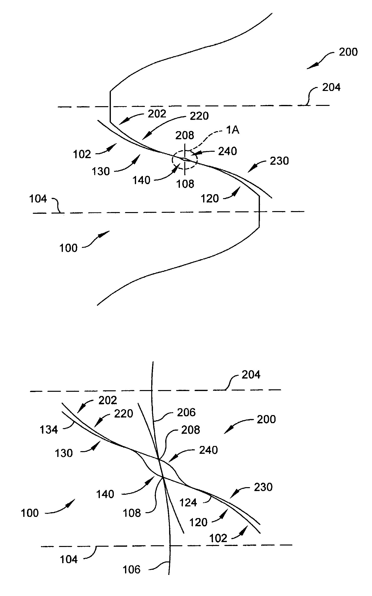
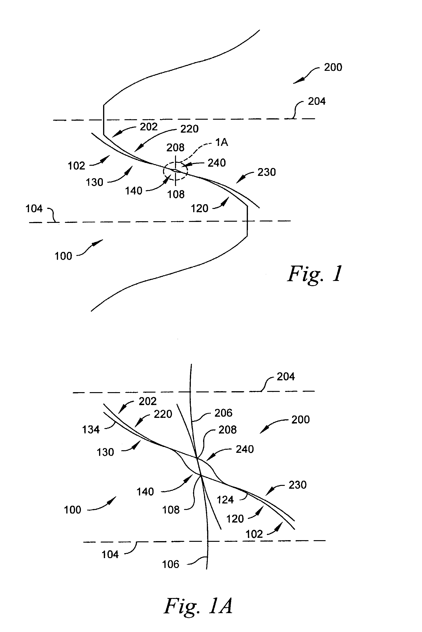
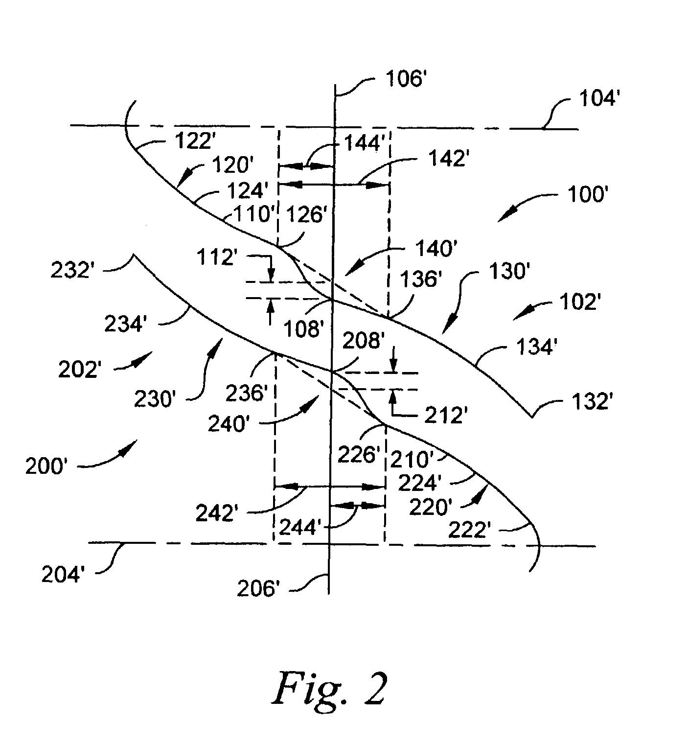
[0023]As set forth in the '892 patent, incorporated by reference in its entirety herein, and well known by those skilled in the art, a family of gears can be defined by either a gear tooth profile, a pinion (or mating gear) tooth profile, the shape of the contact path between the gear tooth profile and the pinion tooth profile, a corresponding basic rack tooth profile or basic cutter tooth profile. As used herein, a family of gears comprises all gears that can be cut by the same basic cutter. The term “basic rack” refers to a gear with an infinite number of teeth spaced along a straight line and is the basic member of the family of gears. The basic rack is the com...


PUM

PropertyMeasurementUnit
Widthaaaaaaaaaa

Abstract

A gear and method for producing the gear. The gear has a gear tooth profile conjugate to a gear basic-cutter tooth-profile having an addendum with a convex portion having an addendum point proximal to a pitch line and a dedendum with a concave portion having a dedendum point proximal to the pitch line. The convex portion is complementary with a corresponding portion of a mating-gear basic-cutter tooth-profile dedendum. The concave portion is complementary with a corresponding portion of the mating-gear basic-cutter tooth-profile addendum. A transition zone between the addendum point and the dedendum point has a predetermined width. The gear basic-cutter tooth-profile has a predetermined half pitch relief at the pitch line and continuity of profile and continuity of slope at the addendum point.

Description

CROSS-REFERENCE TO RELATED APPLICATIONS[0001]This application is related to U.S. Provisional Patent Application No. 60 / 374,655, filed Apr. 22, 2002, and claims the earlier filing date of the provisional application which is incorporated herein by reference.BACKGROUND OF THE INVENTION[0002]The present invention relates to a family of gears having tooth profiles that are conjugate through most of the dedendum and addendum and a transition zone between the dedendum and addendum having no contact at the pitch circles. Additionally, the present invention also relates to a method for manufacturing gears having tooth profiles that are conjugate through most of the dedendum and addendum and that are not conjugate in the transition zone.[0003]In the early Wildhaber-Novikov gears, as described by Chironis in “Design of Novikov Gears”, (a chapter of “Gear Design and Application”, McGraw-Hill, 1967, pp 124–135), the pinion is all-addendum and the gear tooth is all-dedendum. The transverse secti...

Claims


Application Information

Patent Timeline
15 Nov 2005
Publication
US6964210B2
IPC
B23F15/00; B23F21/00; F16H55/08; F16H55/02
CPC
B23F15/00; B23F21/00; F16H55/08; F16H55/0826; Y10T409/101749; Y10T409/103975; Y10T409/10795; Y10T74/19972
Inventors
COLBOURNE, JOHN R.