Heat dissipation device

a heat dissipation device and heat sink technology, applied in semiconductor devices, cooling/ventilation/heating modifications, basic electric elements, etc., can solve the problem that the heat dissipation requirement of modern cpus/psus is difficult to meet the heat dissipation requirement of conventional heat sinks, and achieve the effect of efficient dissipation of heat from heat generating components

Inactive Publication Date: 2005-11-15
GOLD CHARM LTD
View PDF20 Cites 42 Cited by
  • Summary
  • Abstract
  • Description
  • Claims
  • Application Information

AI Technical Summary

Benefits of technology

[0005]Accordingly, an object of the present invention is to provide a heat dissipa

Problems solved by technology

Conventional heat sink is difficult to satisfy h

Method used


Image

  • Heat dissipation device
  • Heat dissipation device
  • Heat dissipation device

Examples


Embodiment Construction

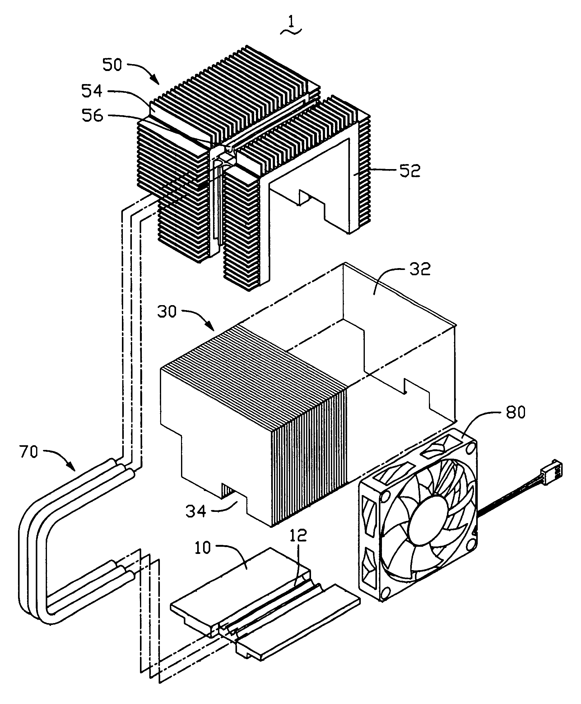
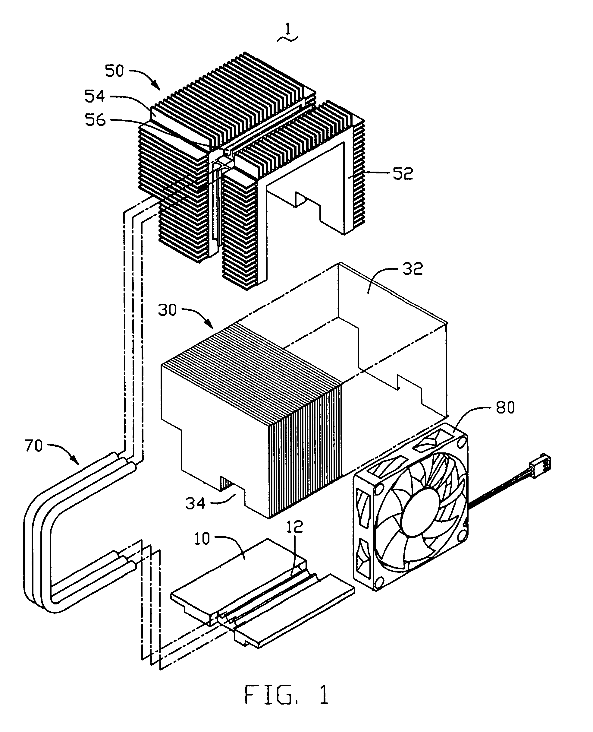
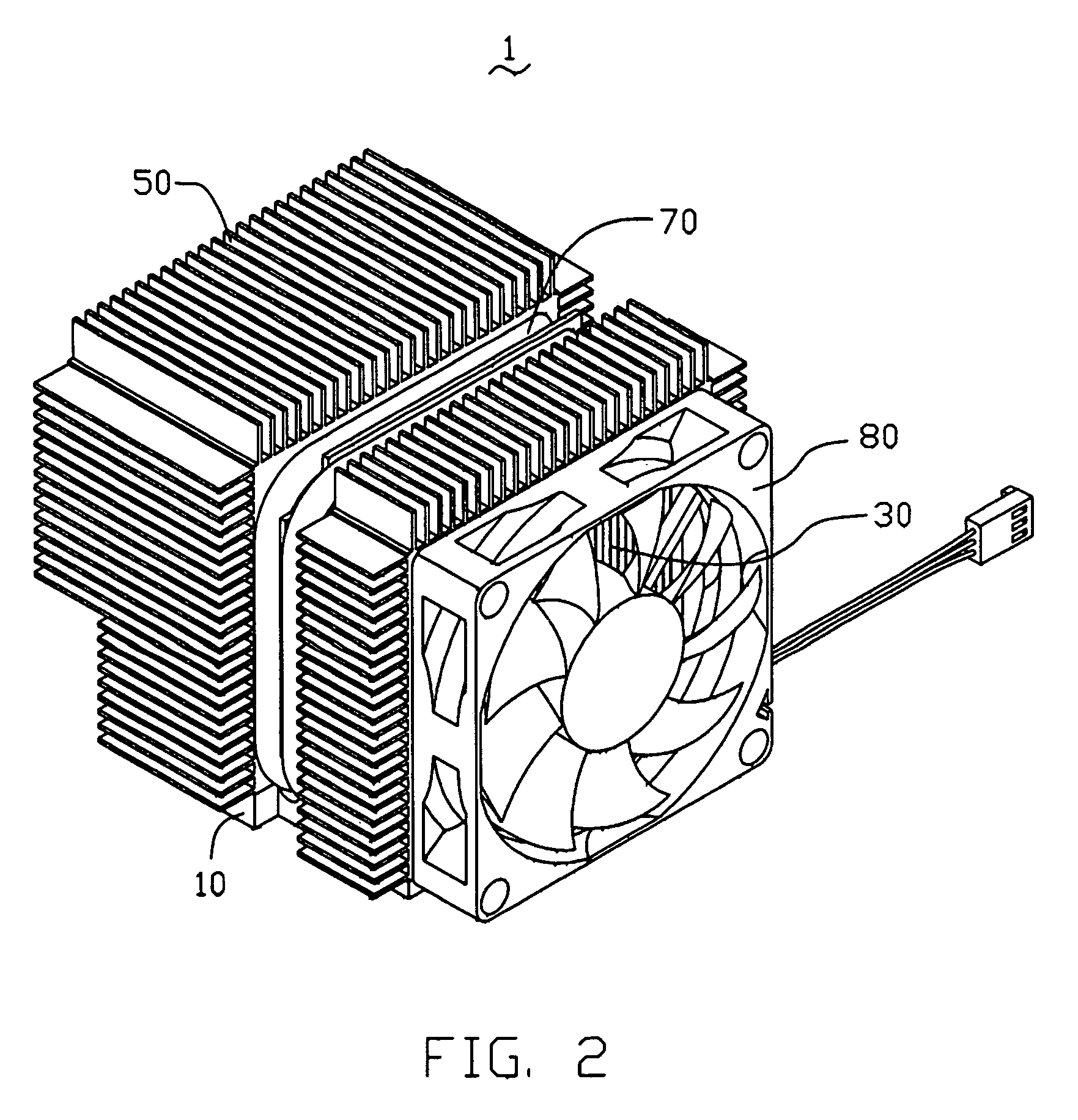
[0011]FIGS. 1–2 show a heat dissipating device 1 in accordance with a preferred embodiment of the present invention. The heat dissipating device 1 comprises a heat receiver 10, a heat sink 30, a fin member 50, a plurality of pipes 70 and a fan 80.

[0012]The heat receiver 10 is made of heat conductive material, such as copper, for contacting with an electronic device such as a CPU (not shown). The heat receiver 10 is board-shaped and defines a plurality of grooves 12 in the top surface thereof for receiving vaporized sections of the pipes 70.

[0013]The heat sink 30 comprises a plurality of parallel and spaced plates 32. Each plate 32 comprises a pair of flanges respectively formed at the top and bottom edges thereof and spaces from adjacent plates with a predetermined distance. A plurality of channels (not labeled) is therefore formed between the plates 32. Each plate 32 defines a cutout at the bottom portion thereof. The cutouts of the plates 32 cooperatively form a passage 34 perpend...


PUM


Abstract

A heat dissipating device assembly includes a heat receiver, a heat sink defining two opposite ends and a plurality of channels formed between the two opposite ends, a fin member cooperating with the heat receiver to enclose the heat sink except the two opposite ends, a plurality of heat pipes connecting the heat receiver with the fin member, and a fan provided adjacent one of the two opposite ends for creating airflow to flow through the channels of the heat sink. The fin member includes a plurality of fins formed at the outer surface thereof for increasing heat dissipating surface of the heat dissipating device assembly.

Description

TECHNICAL FIELD[0001]The present invention relates to heat dissipating devices, and particularly to a heat dissipating device which can efficiently dissipate heat from an electronic component.BACKGROUND[0002]As computer technology continues to advance, electronic components such as central processing units (CPUs), power supply units (PSUs) of computers are made to provide faster operational speeds and greater functional capabilities. When a CPU / PSU operates at a high speed in a computer enclosure, its temperature frequently increases greatly. It is desirable to dissipate the generated heat of the CPU / PSU quickly, for example, by using a heat sink attached to the CPU / PSU in the enclosure. This allows the CPU / PSU and other electronic components in the enclosure to function within their normal operating temperature ranges, thereby assuring the quality of data management, storage and transfer.[0003]In order to promote the heat dissipation effect of the heat sink, fans have been widely u...

Claims


Application Information

Patent Timeline
IPC IPC(8): F28D15/00H01L23/427H01L23/467
CPCH01L23/427H01L23/467H01L2924/0002H01L2924/00F28D15/0275
Inventor YU, GUANGLEE, HSIEH-KUNLU, CUI-JUN
Owner GOLD CHARM LTD
Why Eureka
Try Eureka