
Heat exchanger

a technology of heat exchangers and heat exchangers, which is applied in the direction of manufacturing tools, soldering devices, lighting and heating apparatus, etc., can solve the problems of water drainage, drastically impede efficiency, and suffer the performance of round tube plate fin heat exchangers, so as to eliminate the requirement of fixation

Inactive Publication Date: 2005-11-15
MODINE MFG CO
View PDF66 Cites 213 Cited by
  • Summary
  • Abstract
  • Description
  • Claims
  • Application Information

AI Technical Summary

Benefits of technology

The invention provides a new and improved method of making a heat exchanger that eliminates the need for fixturing during the brazing process. The heat exchanger includes plate fins with tube runs that are vertically arranged in a heat exchanger with horizontal tube runs. The plate fins have slots that are shaped to match the cross-section of the tube runs. The fins are located on a supporting surface with the tube runs in contact with the fins and in fluid communication with the headers. The method includes steps of fitting the tube runs snugly into the fins, locating the assembly on the supporting surface, and subjecting it to an elevated temperature to braze the fins to the tubes. The invention also provides an improved heat exchanger core with increased surface area between the openings without increasing the spacing between adjacent openings.

Problems solved by technology

Particularly when used as evaporators, conventional serpentine louvered fins coupled with horizontal tube placement provides problems with water drainage due to the hold up of water between the fins.
That is to say, it is necessary in evaporator applications that provision be made to drain moisture condensing on heat exchanger parts to prevent freeze-up which would block air flow and drastically impede efficiency.
However, when compared to brazed, parallel flow type heat exchangers, performance of round tube plate fin heat exchangers suffers in three main areas.
As a consequence, poor air side heat transfer results.
A second problem is that mechanical bonds between the tubes and the plate fins conventionally employed in such heat exchangers are incapable of reliably providing intimate, good heat exchange contact between the tubes and the fins and as a result, poor fin-tube bonds frequently reduce heat transfer.
A third problem is that the use of round tubes requires relatively large fin heights (fin height being the length of the fin between the center lines of two adjacent tubes).
These large effective fin heights result in poor fin efficiency.
Still another problem that has sometime occurred in heat exchangers generally is undesirably low air side area.
Consequently, it would be desirable to increase air side surface area without increasing fin height to the point where poor fin efficiency results.

Method used


Image

  • Heat exchanger
  • Heat exchanger
  • Heat exchanger

Examples


Embodiment Construction

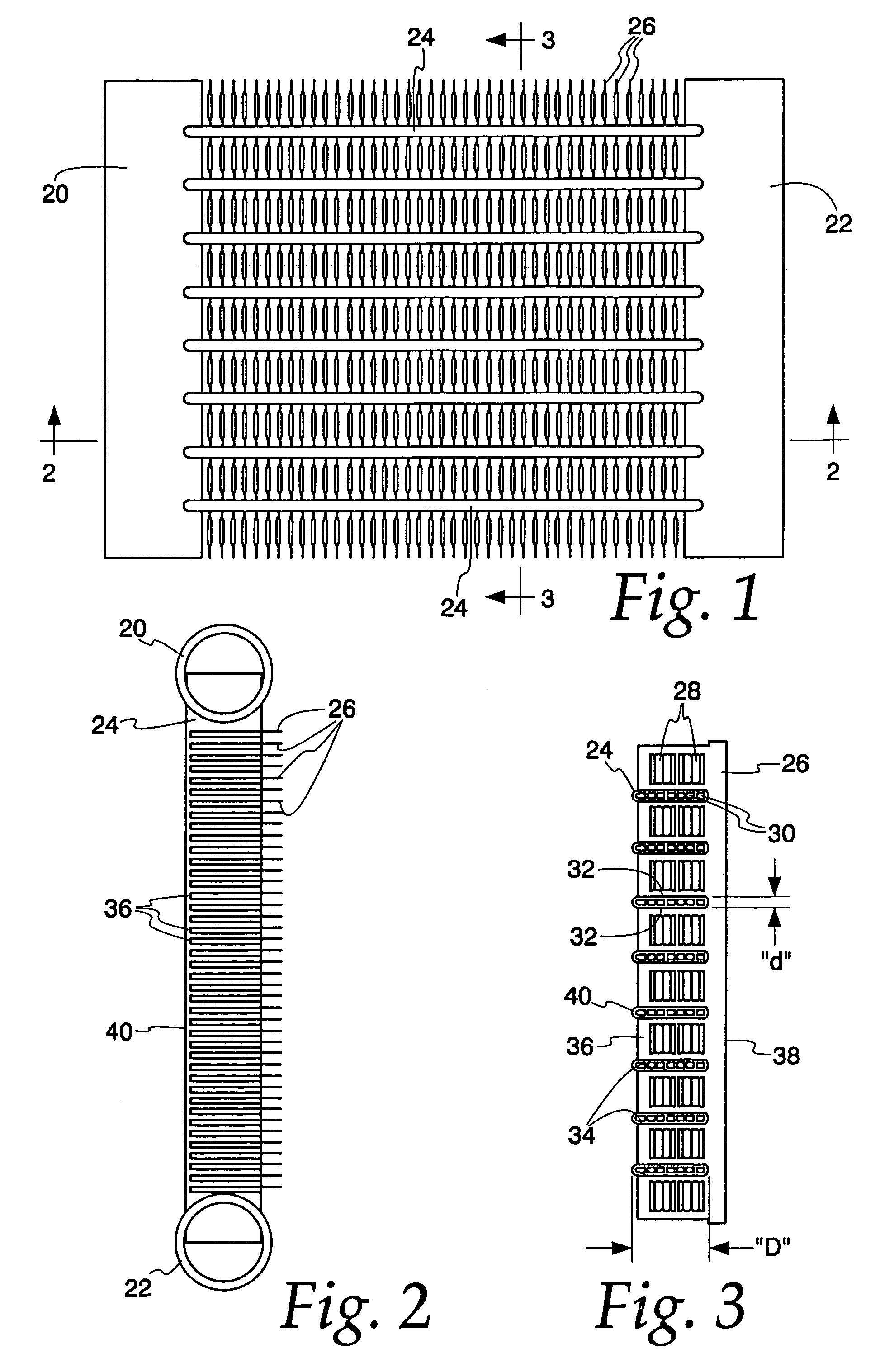
[0044]Exemplary embodiments of the invention will be described in connection with the drawings, frequently in the context of heat exchangers having horizontal tube runs and vertically extending plate fins. However, it is to be understood that no restriction to such orientation is intended except insofar as expressed in the claims. Similarly, while it is preferable that the components of the heat exchanger be of aluminum or aluminum alloy, various performance enhancing features of the invention, such as the use of arcuate plate fins, and / or the use of plate fins which are slotted and open to one side of the fin may be employed with efficacy in non-aluminum heat exchangers; and again, no restriction to aluminum heat exchangers is intended except insofar as expressed in the appended claims.

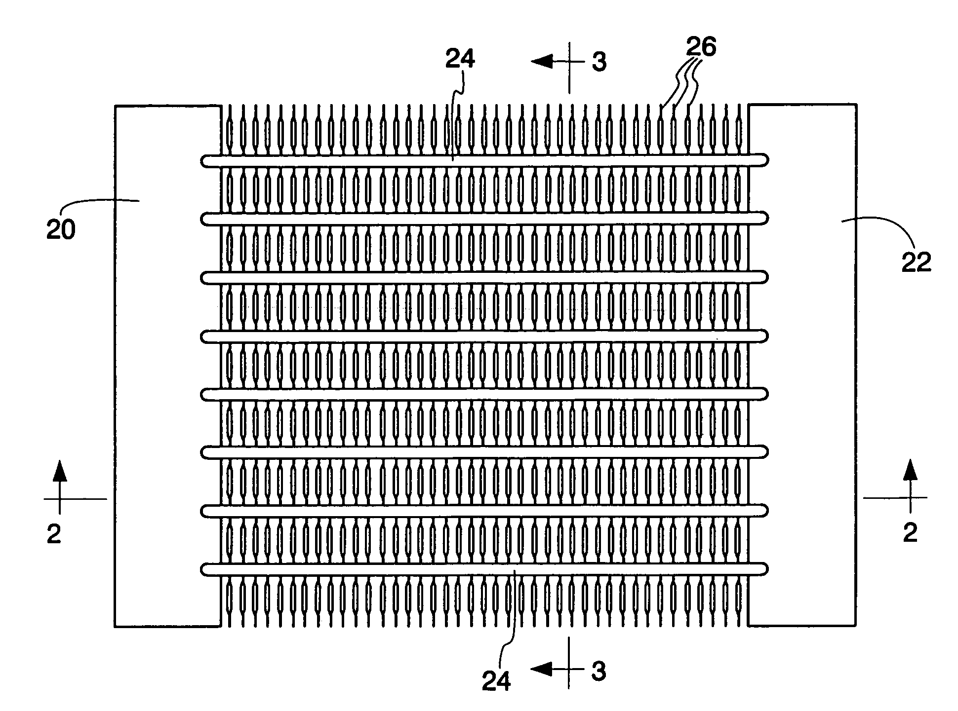
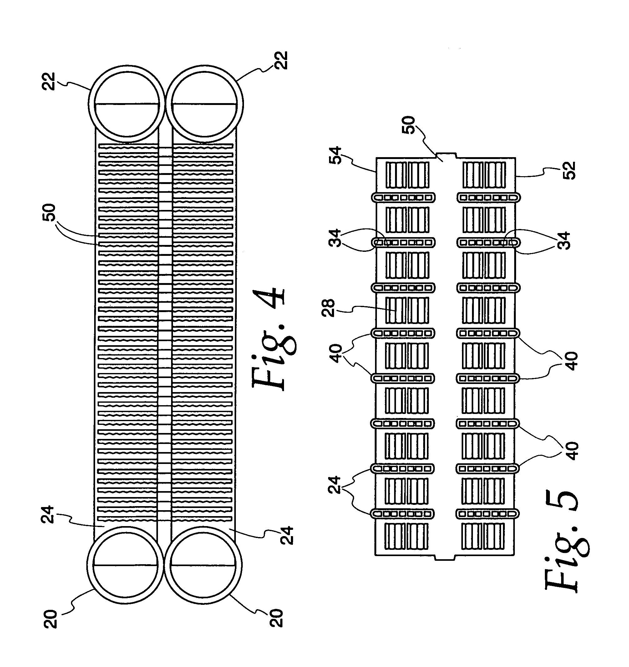
[0045]A first embodiment of a heat exchanger made according to the invention is illustrated in FIGS. 1–3 and is seen to include a pair of vertically extending headers, 20, 22 that are parallel and sp...


PUM

PropertyMeasurementUnit
angleaaaaaaaaaa
dimensionaaaaaaaaaa
widthaaaaaaaaaa

Abstract

Heat exchange inefficiencies found in round tube plate fin heat exchangers are eliminated in an aluminum heat exchanger that includes first and second headers (20), (22) and at least one flattened tube (24), (70) extending between the headers (20), (22). A plurality of generally parallel tube runs are defined and each has opposite edges. A plurality of plate fins (26), (50) are arranged in a stack and each has a plurality of open ended slots (34), one for each run of the tubes (24), (70). Each of the tube runs (24), (70) is nested within corresponding slots (26) and the fins (26), (50) with one of the edges (40) of the tube runs extending outwardly of the corresponding fin (34). The assembly is brazed together.

Description

FIELD OF THE INVENTION[0001]This invention relates to heat exchangers, and more specifically, to a brazed aluminum plate fin heat exchanger.BACKGROUND OF THE INVENTION[0002]In heat exchangers that have a high aspect ratio (the ratio of width to height), it is frequently necessary to locate the tube runs in a generally horizontal plane to minimize cost. Typical of such heat exchangers are evaporators and condensers as may be found in the air conditioning systems of off-highway vehicles, air conditioning systems for recreational vehicles, and in truck refrigeration systems. Particularly when used as evaporators, conventional serpentine louvered fins coupled with horizontal tube placement provides problems with water drainage due to the hold up of water between the fins. That is to say, it is necessary in evaporator applications that provision be made to drain moisture condensing on heat exchanger parts to prevent freeze-up which would block air flow and drastically impede efficiency.[...

Claims


Application Information

Patent Timeline
Patent Type & Authority Patents(United States)
IPC IPC(8): B21D53/08B21D53/02F28F1/02F28F1/32F28D1/053F28D1/047F28D1/04F28F1/10
CPCB21D53/085F28D1/0435F28D1/0476F28D1/0478F28D1/05366F28D1/05383F28F1/022F28F1/32F28F1/325B23K1/0012Y10T29/49373B23K2201/14F28D2021/0085F28F2215/12F28F2215/02F28F2250/02Y10T29/4938Y10T29/4935Y10T29/49364B23K2101/14F28F1/10
Inventor MEMORY, STEPHENHUGHES, GREGORYZHANG, WINSTONROGERS, C. JAMESGROHMAN, CRAIGROBINSON, EDWARDMIELKE, RICHARDWATTELET, JONATHAN P.GABBEY, LAWRENCETRAPP, RICHARD J.
Owner MODINE MFG CO
Learn More