System and method for improved installation and control of concealed plumbing flush valves

a technology for concealed plumbing and flush valves, applied in the direction of valve operating means/release devices, instruments, mechanical equipment, etc., can solve the problems of many errors made in installing these devices, time-consuming and complicated manual installation, and time-consuming and expensive installation work

Active Publication Date: 2005-11-15
SMART WAVE TECH +1
View PDF8 Cites 50 Cited by
  • Summary
  • Abstract
  • Description
  • Claims
  • Application Information

AI Technical Summary

Benefits of technology

[0008]The above problems are addressed by providing a system having separate a user interface module and a valve interface module that are wirelessly linked such that a plumbing installation does not require the routing of wires between a user side and a behind-the-wall side of the plumbing installation.

Problems solved by technology

In the commercial / institutional plumbing industry, there are a number of problems associated with typical water closet and urinal installations in commercial buildings.
A water closet or urinal installation will typically require a time-consuming and complicated manual installation.
In particular, the installation of concealed plumbing fixtures that have mechanical buttons, handles, electronics, pipes and wires requires that each of these components must be precisely located and routed through walls with the result that the installation work is time-consuming and expensive.
For example, the installation of concealed flush valves using mechanical buttons or handles requires that the alignment of the mechanical linkage and the distance from the valve to the front of the exposed wall is precise with the result that many errors are made installing these devices.
Moreover, mistakes made during installation that require post-installation repairs or repairs required due to vandalism or component failure are often difficult and expensive to effect as finished walls, floors and countertop surfaces may have to be removed, dismantled or replaced in order to gain access to and ultimately fix the problem.
Another problem with standard exposed commercial plumbing installations is that, in the case of a water closet, most mechanical and electronic actuators are located behind the water closet fixture.
This arrangement of components requires that the user must reach over the water closet in order to flush the fixture which is unpleasant.

Method used


Image

  • System and method for improved installation and control of concealed plumbing flush valves
  • System and method for improved installation and control of concealed plumbing flush valves
  • System and method for improved installation and control of concealed plumbing flush valves

Examples


Embodiment Construction

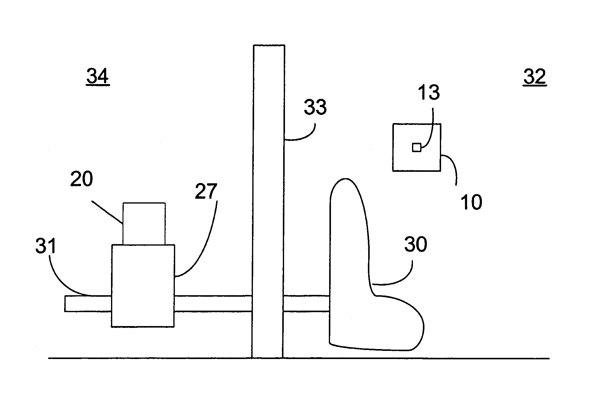
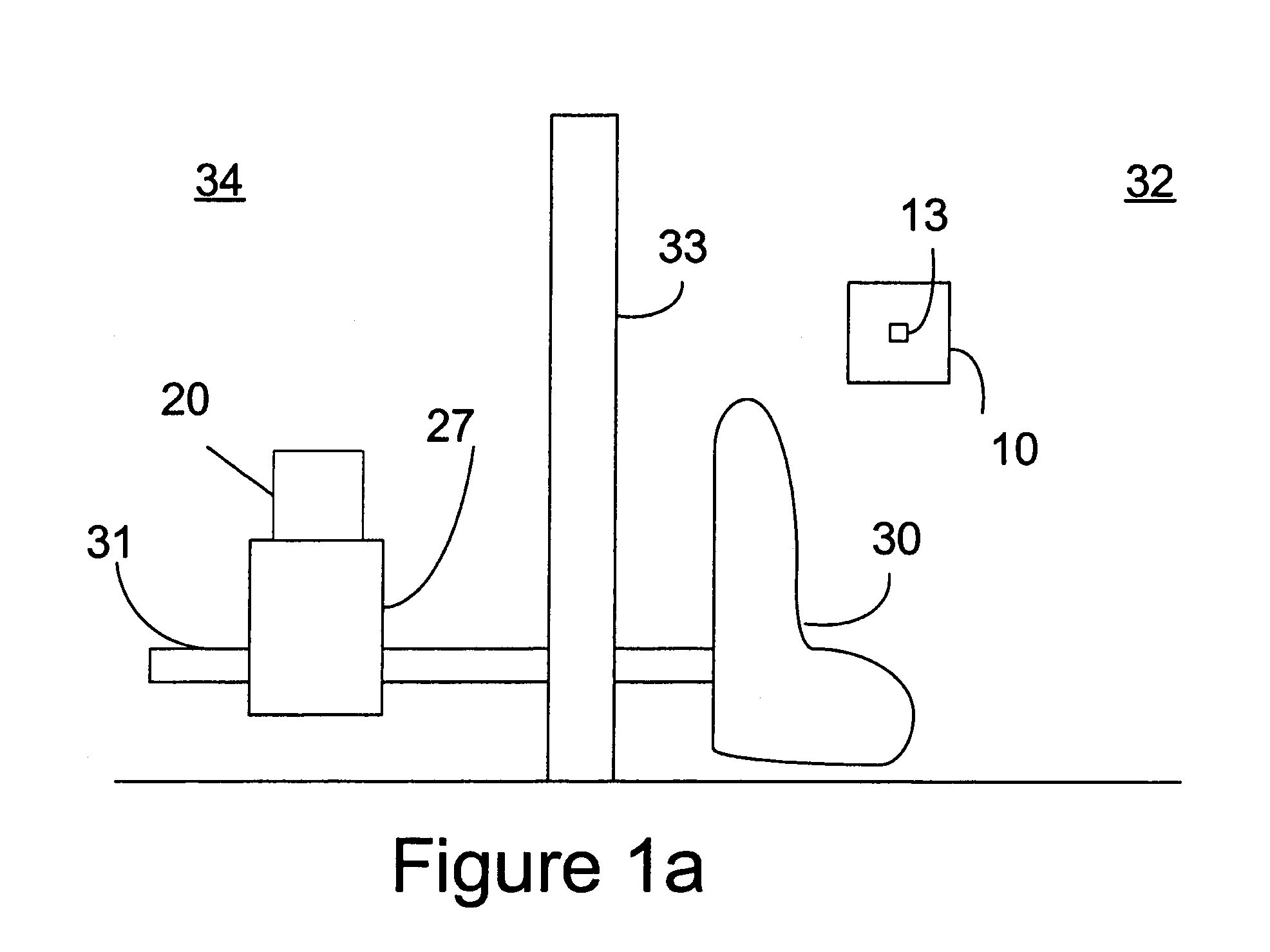
[0028]With reference to the Figures, an improved system and method for installation of concealed plumbing flush valves is described.

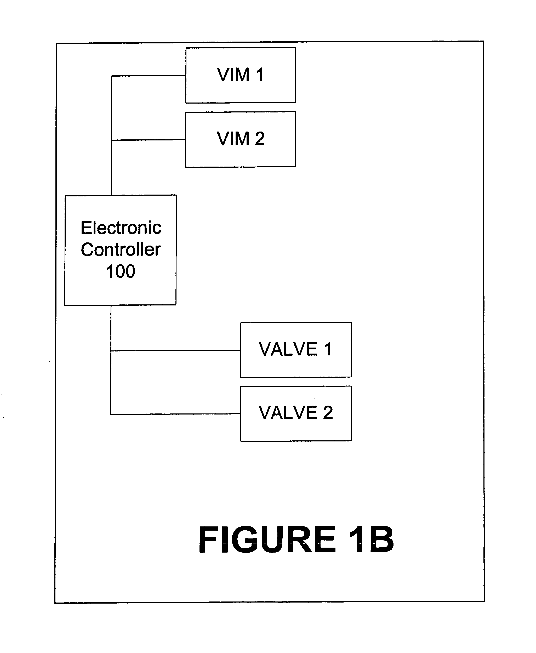
[0029]More specifically, the invention provides a radio frequency (RF) valve control system that replaces mechanical devices that physically link a button or handle to a flush valve as well as electronic valve control systems that are connected to a valve actuator by a cable. The system is characterized by two modules, a user interface module (UIM) which is located on the user side of a plumbing fixture (such as a water closet, faucet, or urinal), and a valve interface module (VIM) operatively connected to a flush valve (or faucet) of the individual plumbing fixture. The UIM generally has the function of providing an RF valve control signal to the VIM and the VIM has the function of receiving, analysing, and responding to the RF valve control signal and to initiate a flush cycle or to initiate a valve control process to control a valve within the water ...


PUM


Abstract

The invention provides a radio frequency (RF) valve control system that replaces mechanical systems that physically links a button or a handle to a flush valve or hard wired electronic control systems that physically links a sensor / electronic switch to a valve actuator within a plumbing installation. The new system is characterized by two modules, a user interface module (UIM) for locating at or adjacent a plumbing fixture (such as a water closet or urinal), and a valve interface module (VIM) operatively connected to a flush valve actuator or a valve in the water supply line of the plumbing fixture. The UIM generally has the function of providing an RF valve control signal to the VIM and the VIM has the functions of receiving, analysing, and responding to the RF valve control signal and sending a signal to the valve actuator to initiate a flush cycle or initiating a valve control process to control a valve within the water supply line to start or stop water flow to the fixture. The system may be deployed as a single UIM / VIM pair or as multiple UIM / VIM pairs within a multi-fixture installation. In each case, each UIM / VIM pair communicates with its respective UIM or VIM in both a learning and active mode.

Description

FIELD OF THE INVENTION[0001]The invention provides a radio frequency (RF) valve control system that replaces mechanical systems that physically links a button or a handle to a flush valve or hard wired electronic control systems that physically links a sensor / electronic switch to a valve actuator within a plumbing installation. The new system is characterized by two modules, a user interface module (UIM) for locating at or adjacent a plumbing fixture (such as a water closet or urinal), and a valve interface module (VIM) operatively connected to a flush valve actuator or a valve in the water supply line of the plumbing fixture. The UIM generally has the function of providing an RF valve control signal to the VIM and the VIM has the functions of receiving, analysing, and responding to the RF valve control signal and sending a signal to the valve actuator to initiate a flush cycle or initiating a valve control process to control a valve within the water supply line to start or stop wat...

Claims


Application Information

Patent Timeline
Patent Type & Authority Patents(United States)
IPC IPC(8): E03D5/00F16K31/02E03C1/05E03D5/10G08C17/02
CPCE03C1/057E03D5/10G08C17/02G08C2201/20
Inventor MARCICHOW, MARTINVUONG, NHON T.WATERHOUSE, PAULZOSIMADIS, PETER
Owner SMART WAVE TECH
Why Eureka
Try Eureka