Hydrodynamic journal foil bearing system

a fluid bearing and journal technology, applied in the direction of bearings, shafts and bearings, rotary bearings, etc., can solve the problems of significant bearing wear, bearing wear, and fluid pressure increasing throughout the channel

Active Publication Date: 2005-11-15
HONEYWELL INT INC
View PDF34 Cites 51 Cited by
  • Summary
  • Abstract
  • Description
  • Claims
  • Application Information

AI Technical Summary

Problems solved by technology

This may result in fluid pressure increases throughout most of the channel.
This contact may result in bearing wear.
These preload forces and high liftoff / touch-down speeds may result in significant bearing wear each time the rotor is started or stopped.
However, this design also increases the contact force between the shaft and foils, resulting in higher start torque before development of the hydrodynamic fluid film.
Conventional foil bearing systems may experience wrapping failure, which may occur when a top foil sticks to a rotating shaft, causing the top foil to undergo tension and tighten around the shaft, in effect, wrapping around the shaft.
This wrapping effect dramatically increases the torque required to turn the shaft, which can prohibit turning or damage the bearing by pulling them out of its anchoring mechanism.
However, manufacturing difficulties, including costs for additional parts, make the use of preload bars or flat circumferential preload springs costly.
Also, the circumferential spring and / or preload bar in the Bosley design and other prior art may keep the top foil from collapsing to the shaft; but the control of radial space between the top foil and the shaft is susceptible to variations in bore diameter and the underspring height.
When the space between the top foil and the shaft becomes too small, too much of the preload from the springs transfers to the shaft through the top foil, dramatically increasing the start torque.
If the space between the top foil and the shaft becomes too large, the fluid film damping will decrease dramatically and the rotor will be susceptible to rotor instability.
The prior art is intended for allowing higher preload forces and higher coulomb damping without higher start torque, but does not improve fluid film damping and some suffer from one or more of the following disadvantages:a) excessive start torque;b) lower preload forces between the foils and the bore, which may cause lower damping forces;c) lower tolerances for manufacturing variations;d) wrapping;e) higher parts costs.

Method used


Image

  • Hydrodynamic journal foil bearing system
  • Hydrodynamic journal foil bearing system
  • Hydrodynamic journal foil bearing system

Examples


Embodiment Construction

[0041]The following detailed description is of the best currently contemplated modes of carrying out the invention. The description is not to be taken in a limiting sense, but is made merely for the purpose of illustrating the general principles of the invention, since the scope of the invention is best defined by the appended claims.

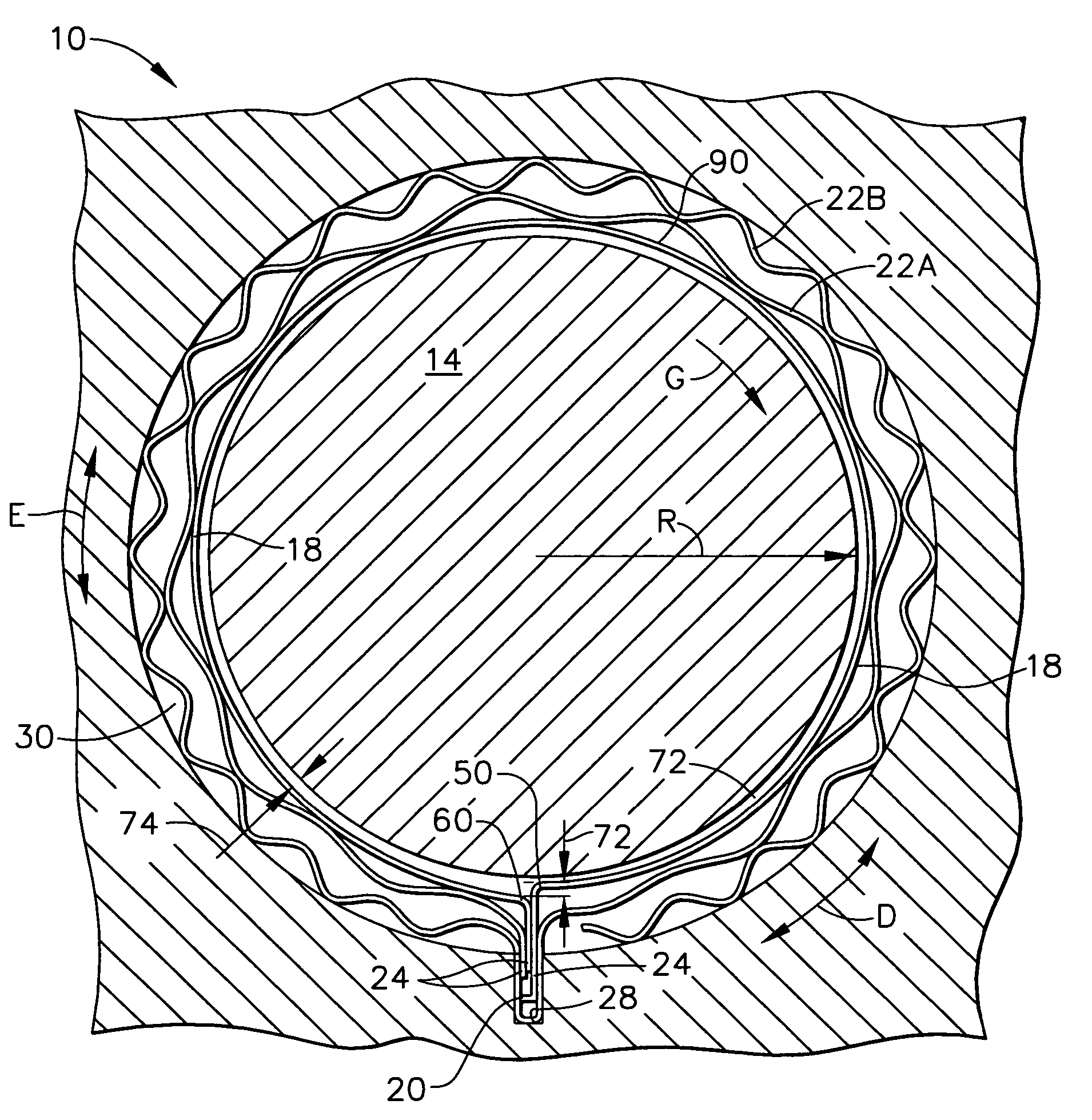
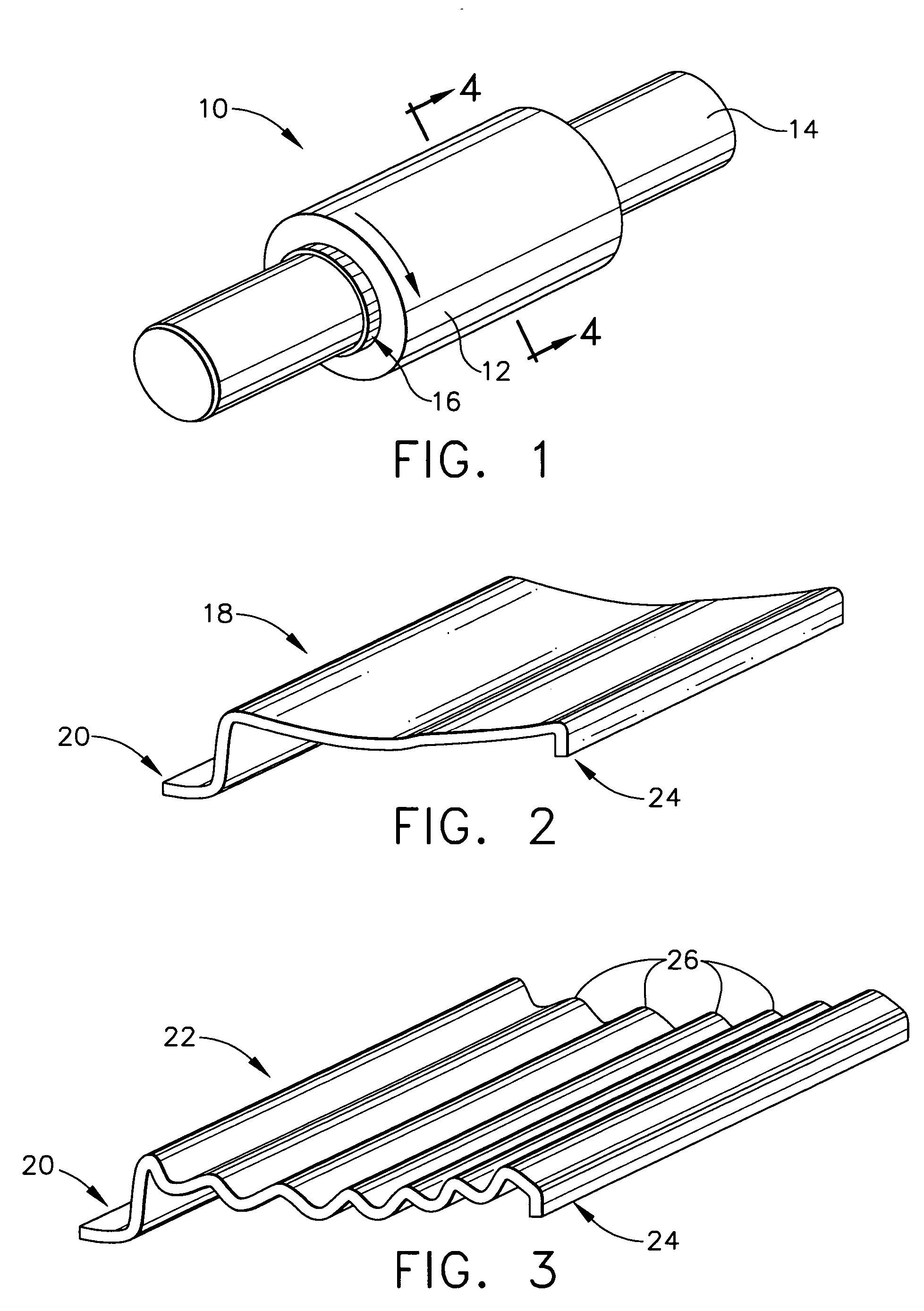
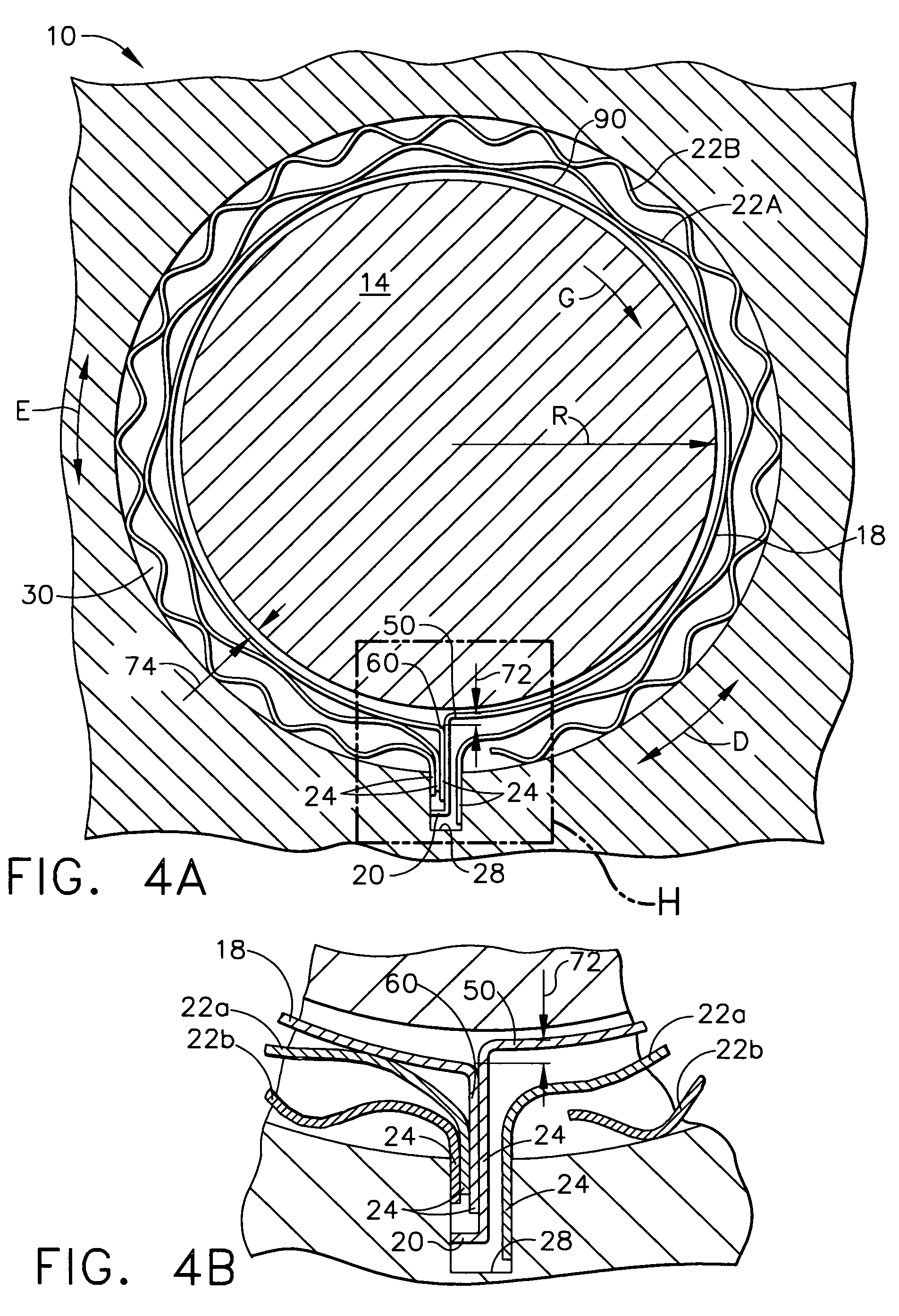
[0042]The invention is useful for high speed rotating machinery. The present invention relates to pneumatic journal bearings supporting a rotating shaft of a variety of high speed rotating systems, such as auxiliary power units for aircraft or air conditioning machines and, more particularly, to a gas foil journal bearing having a foil with both a top foil and plurality of undersprings which have a high supporting capacity of the shaft when highly loaded and a high damping capacity. Additionally, the top foil has a leading edge and a trailing edge that push against each other to maintain the top foil shape when starting or stopping high speed rotating m...


PUM


Abstract

A high load capacity hydrodynamic journal foil bearing system is disclosed, which comprises a top foil and a plurality of undersprings. Preload forces are transferred from the undersprings to internal circumferential compressive forces within a top foil, resulting in low preload forces against the shaft, allowing the shaft to expand at high speeds without increasing the preload forces or overloading the fluid film. One underspring may have a different spring rate than another underspring. The top foil may be normalized to shaft shape and dimensions. These features may be accomplished with using less mechanical parts than other journal foil bearing system designs.

Description

BACKGROUND OF THE INVENTION[0001]This present invention relates generally to radial-type dynamic pressure fluid bearing systems and, in particular, to foil-type fluid bearing systems comprising a stationary retaining member that surrounds the outer circumference of a rotating journal shaft thereby forming an annular cavity. A foil assembly located in the cavity supports the journal.[0002]Fluid bearing systems are used in many diverse applications requiring high speed rotating machinery. Fluid bearing systems generally comprise two relatively movable elements with a predetermined gap therebetween filled with a fluid, such as air. For example, a fluid bearing system may comprise a stationary bearing housing that surrounds a rotating shaft. Under dynamic conditions, gaps form between the relatively moving surfaces supporting a fluid pressure sufficient to prevent contact between the two relatively movable bearing elements.[0003]Hydrodynamic fluid bearings have been developed by using f...

Claims


Application Information

Patent Timeline
Patent Type & Authority Patents(United States)
IPC IPC(8): F16C17/00F16C17/12
CPCF16C17/024F16C27/02F16C2360/24F16C43/02
Inventor KANG, SUN GOOSAVILLE, MARSHALL
Owner HONEYWELL INT INC
Why Eureka
Try Eureka