
Compressor utilizing low volt power tapped from high volt power

a compressor and high voltage technology, applied in the direction of dynamo-electric machines, pump control, rotary/oscillating piston combinations for elastic fluids, etc., can solve the problems of complex operation components, high cost, and high operating cost of refrigerant compressors

Inactive Publication Date: 2005-11-15
SCROLL TECH
View PDF38 Cites 51 Cited by
  • Summary
  • Abstract
  • Description
  • Claims
  • Application Information

AI Technical Summary

Benefits of technology

[0012]The diagnostic control device is powered with the desired low voltage electric power using the existing high voltage power line. Thus, the necessity to feed additional low voltage wiring through any additional inlet openings in the compressor shell is eliminated.

Problems solved by technology

Refrigerant compressors operate under extreme conditions and may have relatively complex operational components.
Compressor operation presents many design challenges.
In addition to the potential for leakage as mentioned above, there is the potential for a variety of operational faults to occur during use as well as during startup and shutdown.
For example, an overcharge or undercharge of refrigerant can hinder compressor performance.
An improperly wired compressor can also result in compression malfunction.

Method used


Image

  • Compressor utilizing low volt power tapped from high volt power
  • Compressor utilizing low volt power tapped from high volt power

Examples


Embodiment Construction

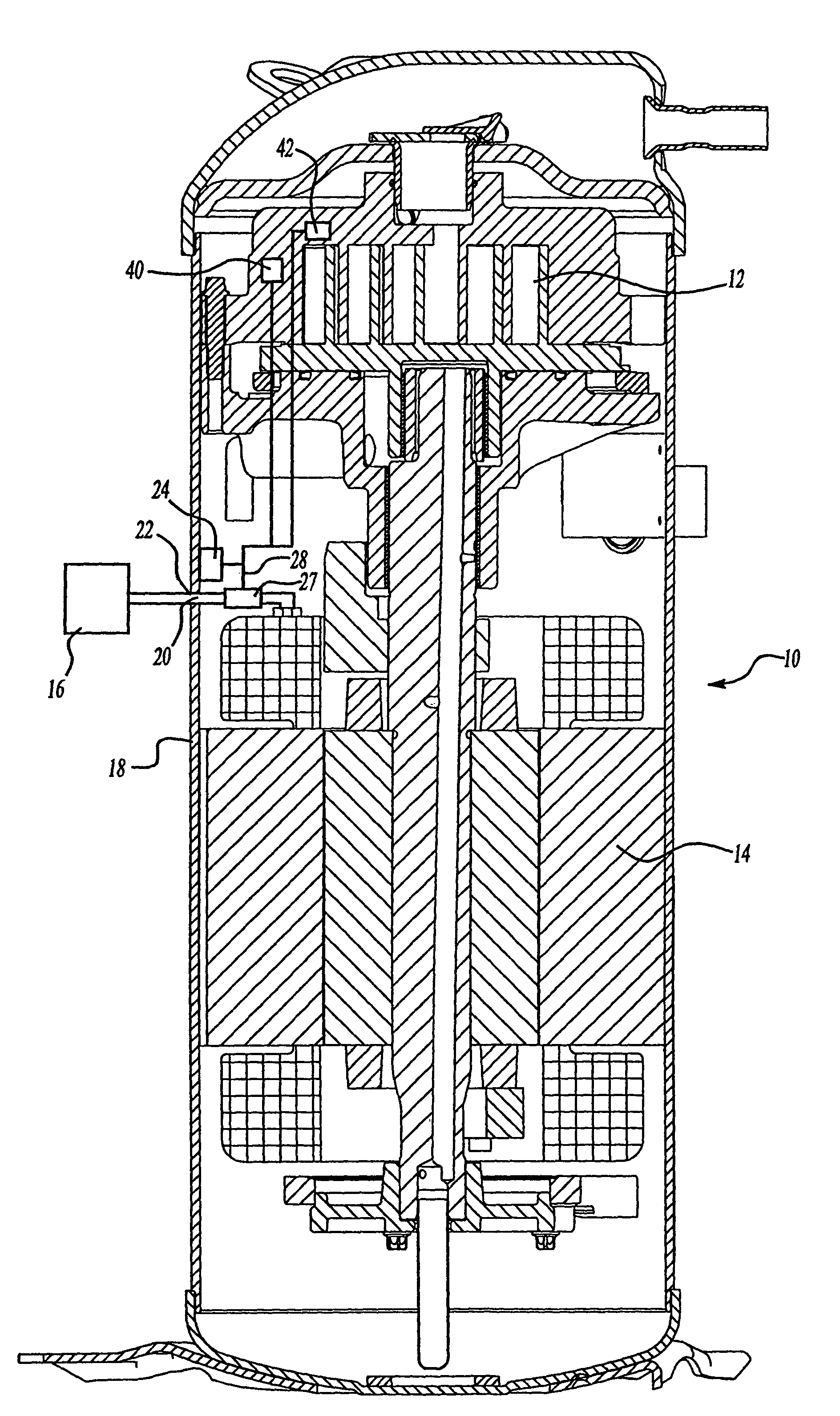
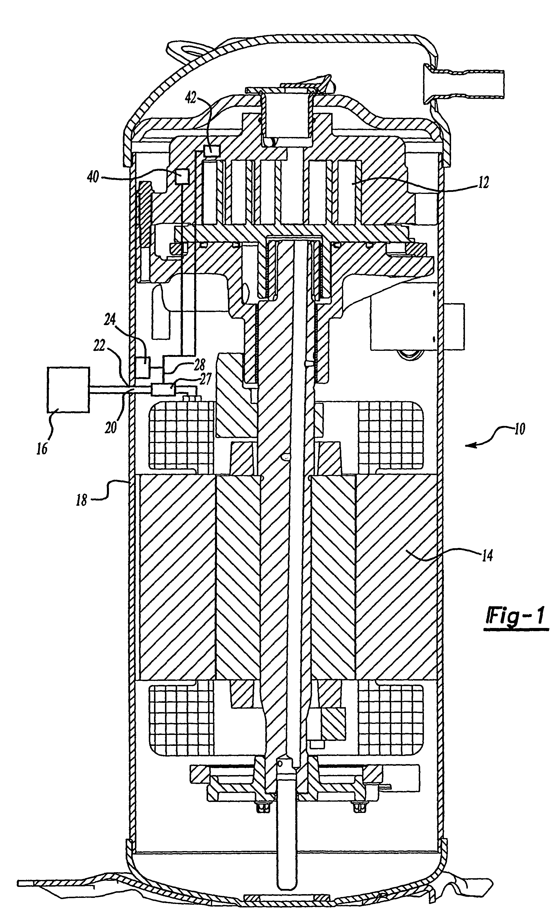
[0016]A sealed compressor 10 is illustrated generally and schematically in FIG. 1. It should be understood that compressor 10 is preferably incorporated into a refrigerant cycle, such as that typically found in air conditioning or other cooling or heating cycles.

[0017]A compressor pump unit, as that typically utilized in a scroll type compressor, is schematically shown at 12. The scroll compressor pump unit 12 is driven by electric motor 14. Electric motor 14 is powered by a high voltage outside power source 16. The power source may be three phase, or single phase. Compressor pump unit 12 and electric motor 14 are housed in sealed compressor shell 18. The high voltage electric power from outside power source 16 is fed to motor 14 by way of incoming power line 20 which enters compressor shell 18 through inlet opening 22.

[0018]A diagnostic control device 24 is provided at a location within the compressor shell 18. Diagnostic control device 24, which is preferably a microprocessor, can...


PUM


Abstract

Low voltage electrical power is supplied to a diagnostic control device in a sealed compressor. Electrical power is tapped from a high voltage power line and transformed to low voltage power that in turn operates the diagnostic control device. The diagnostic control device and the electric voltage transforming system are housed within the sealed compressor shell, thus eliminating the need for additional openings in the compressor shell. Other low voltage devices can be powered in this way.

Description

[0001]This application is a continuation of Ser. No. 10 / 375,442, filed Feb. 27, 2003 Now U.S. Pat. No. 6,641,368 which was a divisional of 09 / 562,984, filed May 1, 2000 Now U.S. Pat. No. 6,588,126.BACKGROUND OF THE INVENTION[0002]This invention relates to a system provided within the shell or sealed housing of a compressor for converting high voltage electric power from a single power source to low voltage electric power for powering the auxiliary compressor systems, such as a diagnostic control device.[0003]Compressors are utilized to compress a refrigerant as part of a refrigerant cycle in cooling systems. Modern compressors for refrigerant compression are typically enclosed within a sealed housing. Typically compressors are driven by an electric motor which receives high voltage electric power from an outside electrical power source by way of a power line extending through an opening in the sealed housing. It is essential that all openings through the sealed housing are well seal...

Claims


Application Information

Patent Timeline
IPC IPC(8): F04C23/00H02K11/00F04C28/28
CPCF04C23/00F04C28/28H02K11/0047H02K11/0073H02K11/0078H02K11/0094F04C2270/80H02K11/001H02K11/20H02K11/25H02K11/33H02K11/35
Inventor HAHN, GREGSUN, ZILIZAMUDIO, CARLOSHUGENROTH, JASONBARITO, THOMASBUSH, JAMES W.HILL, JOE T.WILLIAMS, JOHN R.
Owner SCROLL TECH
Learn More