Tissue opening locator and everter and method
a tissue opening and locator technology, applied in the field of tissue opening locators and everters and methods, can solve the problems of difficult positioning and access of other wounds in the vasculature of patients, the wound will reopen and begin bleeding, and the other wounds will be difficult to locate and access, so as to improve the healing of the wound, facilitate re-entry, and reduce the effect of scarring
- Summary
- Abstract
- Description
- Claims
- Application Information
AI Technical Summary
Benefits of technology
Problems solved by technology
Method used
Image
Examples
second alternate embodiment
of the Retractor
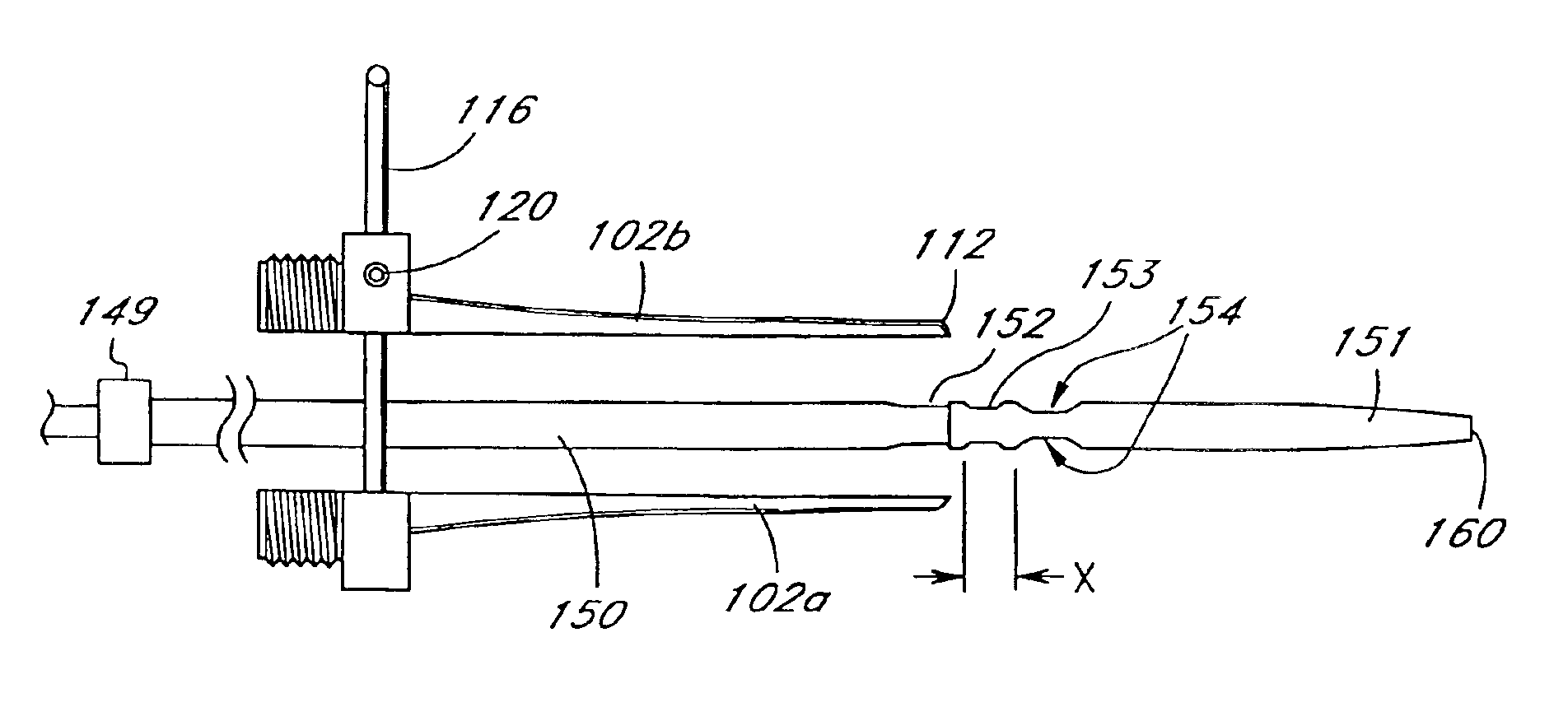
[0073]Yet another embodiment of the retractor of the present invention is illustrated in FIGS. 21 and 22. The retractor 200 comprises a body portion 202 having a distal end 204, and a broader, collar portion 206 at its proximal end 205. Like the embodiment described above, this retractor 200 is formed in two halves 202a, 202b and preferably has a tapered distal end 204. Each half of the body of the retractor 202a, 202b, has a semicircular groove 208 on its flat internal surface 209. When the two halves 202a, 202b are joined together, the semi-circular grooves 208 form a channel 210 running through the interior of the device 200, extending from the proximal end 205 to the distal end 204.
[0074]The collar 206 of the device 200 includes a pin assembly 212 comprising two parallel pins 212a, 212b attached at one end to a handle 212c, and two set screws 214a, 214b. As illustrated in FIG. 22, the pins 212a, 212b traverse guide passages 216a, 216b bored through the collar reg...
third alternate embodiment
of the Retractor
[0075]Still another embodiment of the retractor of the present invention is illustrated in FIGS. 28 and 29. The retractor 300 comprises a distal body portion 302, and a proximal handle portion 304. The distal body portion 302 of the retractor 300 is formed in two portions or halves 302a, 302b. At the distal end 306 of the body portion 302, a retracting portion 308 extends away from, and at an angle to the body portion 302. Preferably, the retracting portion 308 extends substantially perpendicular to the body portion 302. The retracting portion 308 is also formed in two separable portions or halves 308a, 308b. Each of these portions 308a, 308b can be semi-circular in shape, or have a semicircular groove 312 in its flat, internal surface (FIG. 29). The external surfaces are preferably rounded, and tapered toward the distal end 310. When the two portions 308a, 308b are brought together such that the two portions abut one another, as seen in FIG. 28, a channel 314 is for...
fourth alternate embodiment
of the Retractor
[0078]Yet another embodiment of the retractor of the present invention is illustrated in FIGS. 48-50. The retractor 600 comprises a distal body portion 602 and a proximal handle portion 604. The distal body portion 602 of the retractor 600 is formed in two portions or halves 602a, 602b. At the distal end 606 of the body portion 602, a retracting portion 608 extends away from, and at an angle to, the body portion 602. Preferably, the retracting portion 608 extends substantially perpendicular to the body portion 602. The retracting portion 608 is also formed in two separable portions or halves 608a, 608b. Each of these portions 608a, 608b preferably has a semi-circular groove 612 in its internal surface. The external surfaces are preferably rounded, and tapered toward the distal end 610. When the two portions 608a, 608b are brought together such that the two portions abut one another, as seen in FIG. 49, a channel 614 is formed through the interior of the retracting po...
PUM
| Property | Measurement | Unit |
|---|---|---|
| Length | aaaaa | aaaaa |
| Distance | aaaaa | aaaaa |
| Length | aaaaa | aaaaa |
Abstract
Description
Claims
Application Information
 - R&D
- Intellectual Property
- Life Sciences
- Materials
- Tech Scout
- Unparalleled Data Quality
- Higher Quality Content
- 60% Fewer Hallucinations
Browse by: Latest US Patents, China's latest patents, Technical Efficacy Thesaurus, Application Domain, Technology Topic, Popular Technical Reports.
© 2025 PatSnap. All rights reserved.Legal|Privacy policy|Modern Slavery Act Transparency Statement|Sitemap|About US| Contact US: help@patsnap.com


