Method and apparatus for quality control in the manufacture of foundry cores or core packets

a technology of quality control and foundry cores, applied in the field of object recognition, can solve the problems of not being able to detect defects, not only in the immediate vicinity of the shooting device, damage to mold parts and/or tools, etc., and achieve the effect of avoiding damage to the camera or its sensitive lens

Inactive Publication Date: 2005-11-15
HOS HOTTINGER SYSTEMS GBR
View PDF23 Cites 23 Cited by
  • Summary
  • Abstract
  • Description
  • Claims
  • Application Information

AI Technical Summary

Benefits of technology

[0013]In accordance with the invention, it has been recognized that it will also be possible to detect with a single camera irregularly shaped objects, for example, objects with undercuts, niches, cutouts, etc., as regards possible defects, when a very special illumination is provided. Deviating from previously known methods of the kind under discussion, one uses for illuminating the object being examined at least two light sources adapted for sequential and color differentiation. The two light sources illuminate the object from different directions or angles—one after the other or in groups—namely according to the geometry of the particular object. According to the arrangement of the light source relative to the particular object, a shadow of a part of the object is projected onto the base or onto other parts of the object, so that the object can be “extended” or “spread” by means of a shadow cast. In other words, the skillful arrangement of the light sources permits projecting regions that are otherwise not recognizable with a single camera, from their “concealed” position, and recording same as quasi additional image information supplementing the contours of the object. Thus, it is possible to perform a very satisfactory examination of critical regions, which are especially susceptible to possible defects, and to even enlarge them by a suitable projection for purposes of such an—optical—examination, thereby promoting in turn a satisfactory detection.
[0030]Concretely, predeterminable regions of the recorded image could be adapted for extraction or elimination. For the extraction and / or elimination, it would again be possible to predetermine threshold values or gray-scales values corresponding to the threshold values. In this process, the regions of interest can be easily marked for interactive processing via a monitor. Regions prone to defects or damage may be examined with very special attention. In this process, it is possible to reduce the data quantity as a whole. An individual parameterization of the individual regions of interest (RoI) leads to a further increase in the detection performance.

Problems solved by technology

As previously mentioned, the defective cores responsible for these rejects could originate not only from defects in the tool of the core shooting machine, but also from direct damage to the cores during their handling, transportation, or assembly.
In any event, it is not justifiable to be able to detect defects and thus rejects only after completing the casting operation, or during the inspection of the cast parts that have already cooled.
Moreover, damage to mold parts and / or tools may occur not only in the immediate vicinity of the shooting device, but rather also in any handling of the mold part and / or tool, during transportation, in the machining of the mold parts, during the cleaning of the tools, and in particular also during the assembly of the mold parts to whatever shape of a mold packet.
Last but not least, the visual control as addressed in DE 44 34 798 A1 is not practicable, inasmuch as it is not possible to observe the tool constantly within the scope of a fully automatic production.
Even if one performed such a visual observation or inspection, the fate of an ejected core that is to be transported, machined, or assembled to a packet, would be left fully open, inasmuch as defects or damage may also occur during the handling or machining of the cores, during the transfer of the cores, or even during the assembly of the cores to packets.
Both variants require a considerable expenditure for apparatus, and therefore are problematic for cost reasons alone.
Furthermore, the arrangement of a plurality of cameras interferes with the direct surroundings of the particular core, and thus with the manipulators being used in this region.

Method used


Image

  • Method and apparatus for quality control in the manufacture of foundry cores or core packets
  • Method and apparatus for quality control in the manufacture of foundry cores or core packets
  • Method and apparatus for quality control in the manufacture of foundry cores or core packets

Examples


Embodiment Construction

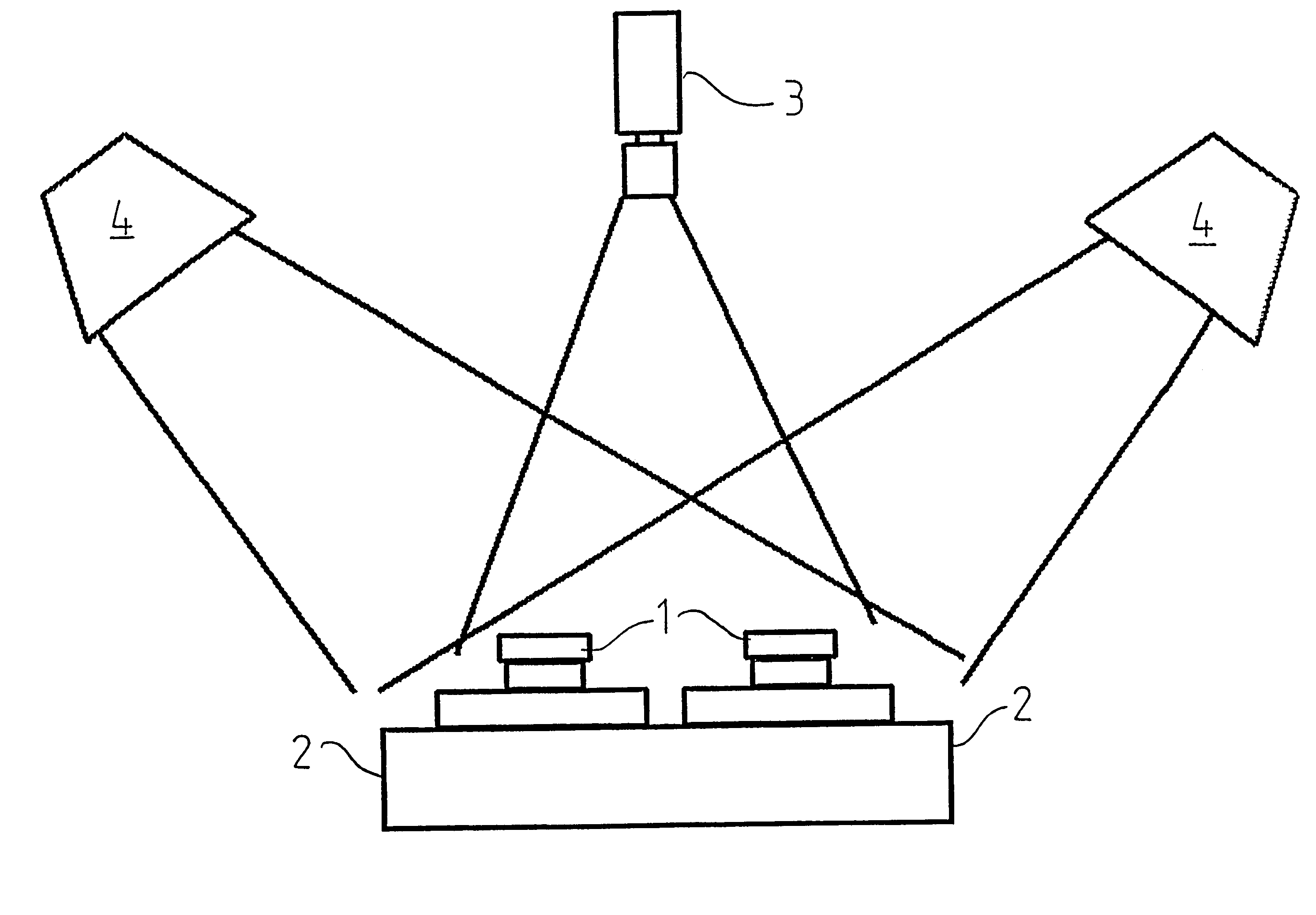
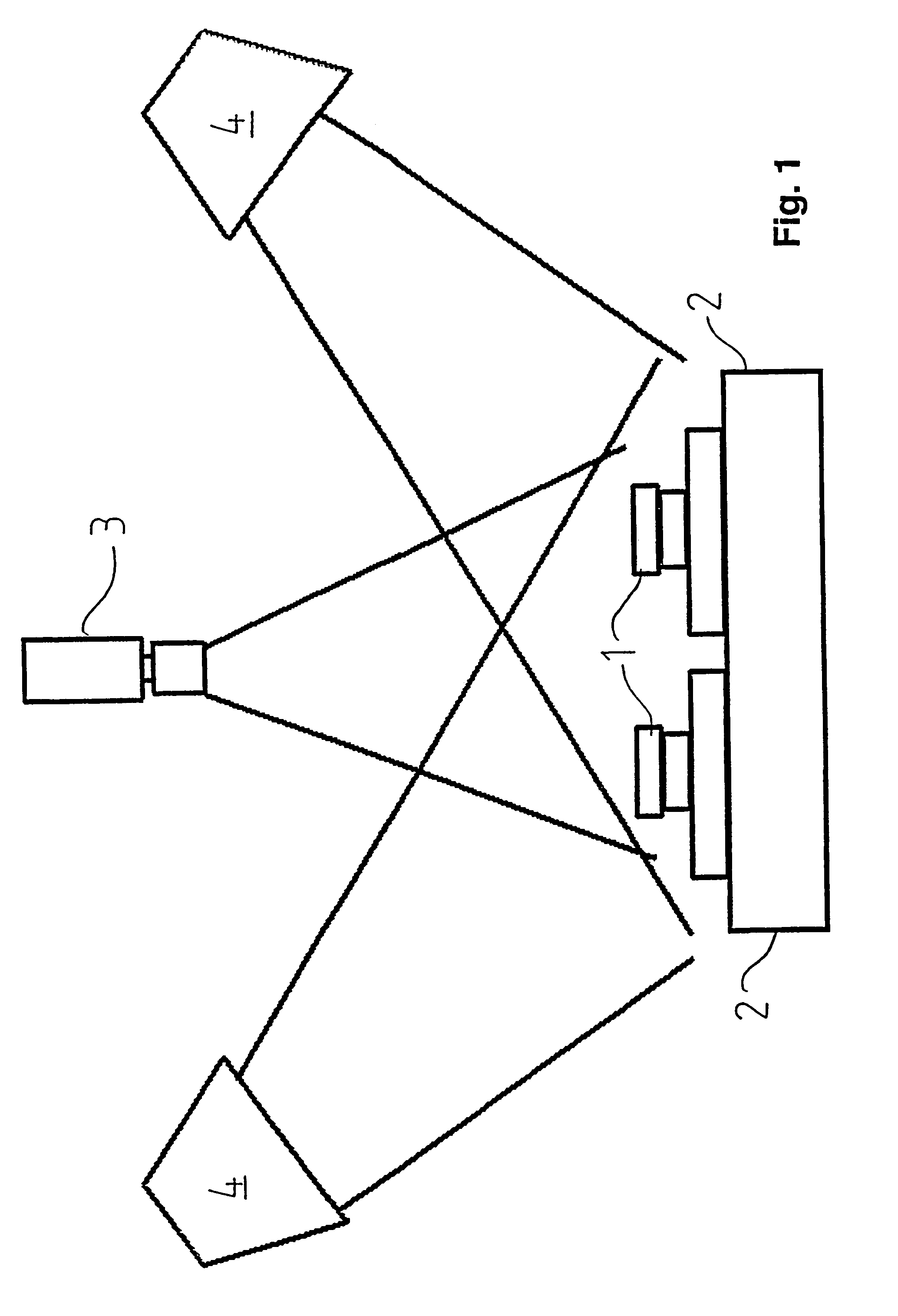
[0035]The embodiment shown in FIG. 1 is an apparatus for detecting defects on shot cores 1. In the illustration, two cores 1 are placed on a base 2, which may be a pallet for transportation.

[0036]The apparatus comprises a camera 3 and two light sources 4, which illuminate cores 1 from different directions or angles, so that the camera 3 detects not only cores 1 in accordance with their contours, but also shadows caused by light sources 4.

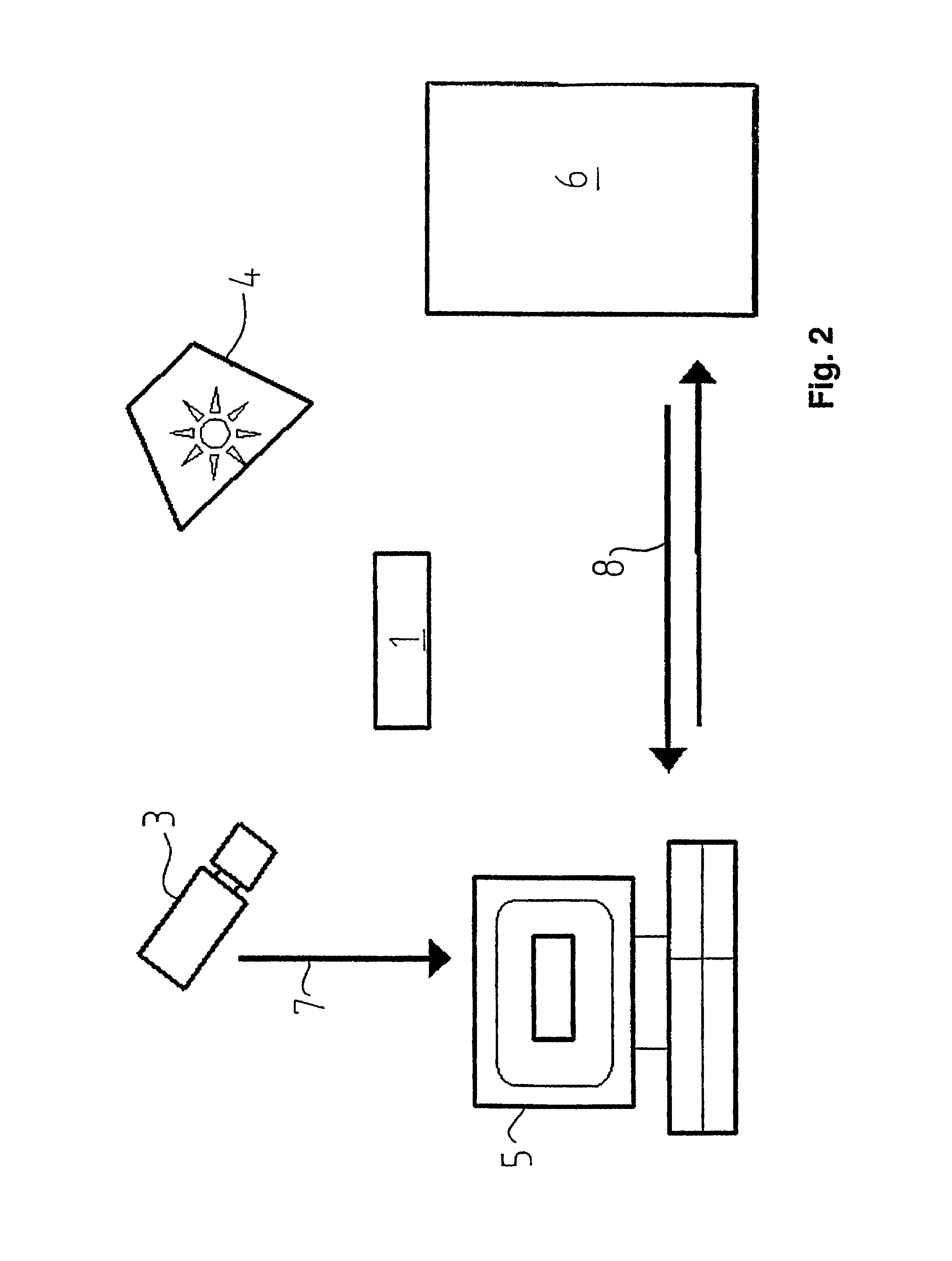
[0037]As shown in FIG. 2, the camera 3 and light sources 4 are used for recording the images of core 1. In this connection, the camera 3 and likewise the light source 4 may be controlled via a processor. Specifically, in the illustrated embodiment, a PC 5 is provided, which receives images 7 that are taken by camera 3. The embodiment shown in FIG. 2 further includes a process control by means of a stored program control (SPC) 6. The stored program control (SPC) 6 communicates with PC 5, i.e., it transmits process signals and result signals 8.

[0038]I...


PUM

PropertyMeasurementUnit
areaaaaaaaaaaa
color differentiationaaaaaaaaaa
metallicaaaaaaaaaa

Abstract

A method and an apparatus for object recognition, in particular defect detection on workpieces, such as shot cores (1) or core packets, wherein the object is illuminated by a light source (4) and recorded and detected by means of a camera (3), and wherein the data obtained from the recording are processed or, if need be, stored by means of a computer. The object is illuminated by a least two light sources (4) from different directions or angles, and the camera (3) records the object and the shadows resulting from the illumination.

Description

BACKGROUND OF THE INVENTION[0001]The invention relates to a method of recognizing objects, in particular detecting defects on workpieces, preferably on shot cores or core packets, wherein the object is illuminated by a light source and recorded or detected by means of a camera, and wherein the data obtained from the recording are processed and, if need be, stored by means of a computer.[0002]Furthermore, the invention relates to an apparatus for recognizing objects, in particular for applying the method according to the invention.[0003]In generic terms, the invention quite generally relates to a method for recognizing objects or detecting defects on workpieces. Quite particularly, this method is suited for detecting defects on shot cores or core packets. To this extent, the invention also relates, among other things, to the field of foundry practice.[0004]For casting mold parts of any kind, foundry cores or molds are made in most cases in separate pieces, combined, and joined to a c...

Claims


Application Information

Patent Timeline
Patent Type & Authority Patents(United States)
IPC IPC(8): G01N21/88G01B11/30B22C9/00B22C15/268G01N21/89G06T1/00
CPCG01N21/8806G01N2021/8845G01N2021/8918
Inventor BEYERER, JURGENSEIRAFFI, MOHAMMED ALI
Owner HOS HOTTINGER SYSTEMS GBR
Why Eureka
Try Eureka