Supercharge Your Innovation With Domain-Expert AI Agents!

Transflective LCD (Liquid Crystal Display) panel and method of constructing the same

a technology of liquid crystal display and transparent panel, which is applied in the direction of optics, instruments, radio frequency controlled devices, etc., can solve the problems of forming uneven brightness distribution throughout the length, reducing the contrast ratio, and requiring longer response time to perform the transition

Active Publication Date: 2005-11-15
AU OPTRONICS CORP
View PDF4 Cites 2 Cited by
  • Summary
  • Abstract
  • Description
  • Claims
  • Application Information

AI Technical Summary

Benefits of technology

"The present invention provides a transflective LCD panel that has uniform brightness throughout the entire length when a voltage is passed through the LCD panel. The panel includes a first substrate, a second substrate, and a plurality of electrode layers and a liquid crystal layer sandwiched between the electrode layers. The electrode layers cooperatively define a transmission domain and a reflective domain that is shorter than the transmission domain. The metal electrode layer and the spacer layer cooperatively define the reflective domain. The technical effect of the invention is to provide a display panel that can provide both transmission and reflection of light for improved viewing angles and brightness."

Problems solved by technology

One drawback of the aforesaid conventional t transflective LCD panel 10 resides in that not all the liquid crystal molecules in the liquid crystal layer 18 extend parallelly to the electric field when voltage is applied thereon, thereby lowing the contrast ratio and consequently forming uneven distribution of brightness throughout the entire length thereof.
In addition, it takes longer response time to perform the transition from their initial alignment to the displayable alignment.
However, the transflective LCD panel of Vertical Alignment mode suffers from a viewable problem.
When the LCD is used outdoor, the ambient light is so strong that the reflection of sunlight from the surface of the display screen overwhelms any light coming through the LCD panel.

Method used


Image

  • Transflective LCD (Liquid Crystal Display) panel and method of constructing the same
  • Transflective LCD (Liquid Crystal Display) panel and method of constructing the same
  • Transflective LCD (Liquid Crystal Display) panel and method of constructing the same

Examples


Embodiment Construction

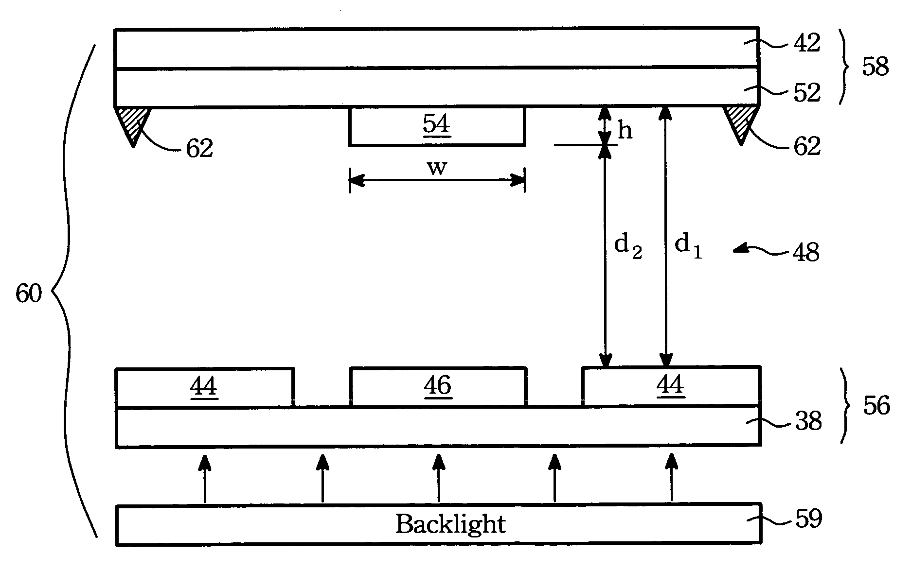
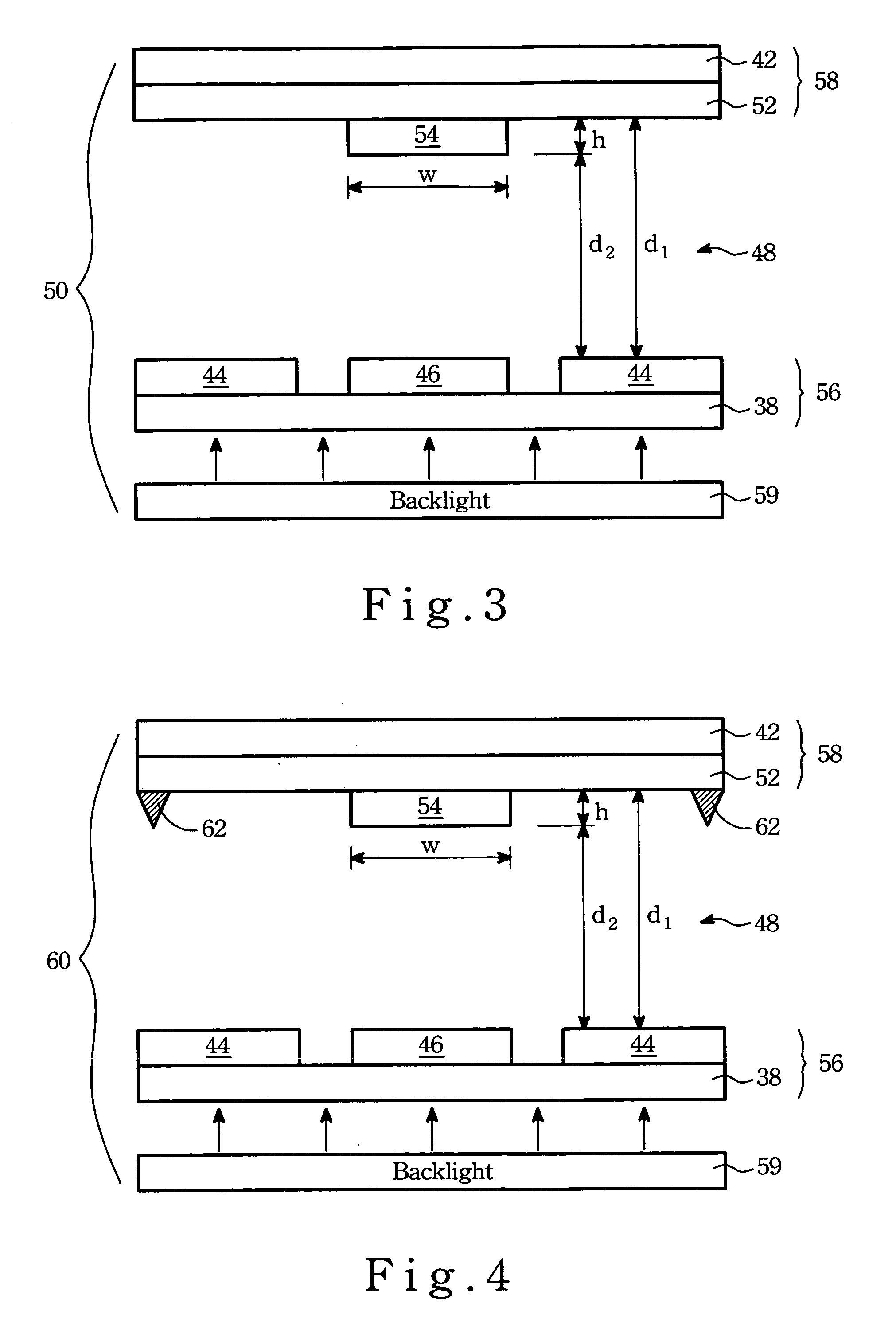
[0024]Referring to FIG. 3, a liquid crystal unit 50 of a transflective LCD panel according to the present invention is shown to include a first substrate 38, a second substrate 42, a plurality of transparent first electrode layers 44, at least one metal electrode layer 46, a liquid crystal layer 48, a transparent second electrode layer 52 and a spacer layer 54. The liquid crystal unit 50 of the transflective LCD panel is divided into a first panel part 56 consisting of the first substrate 38, the first electrode layers 44 and the metal electrode layer 46, and a second panel part 58 consisting of the second electrode layer 52 and the second substrate 42. The liquid crystal layer 48 is sandwiched between the first and second panel parts 56,58.

[0025]As illustrated, the first and second substrates 38,42 are made from transparent glass material, serving as base substrates respectively. In fact, the present transflective LCD panel is an active matrix LCD panel so that the first substrate ...


PUM

PropertyMeasurementUnit
widthaaaaaaaaaa
widthaaaaaaaaaa
widthaaaaaaaaaa

Abstract

A transflective LCD panel includes a first substrate and a second electrode layer sandwiching a liquid crystal layer therebetween. Two first electrode layer are fabricated on the first substrate facing the second electrode layer. A metal layer fabricated on the first substrate is disposed between two of the first electrode layers. A spacer layer is fabricated on the second electrode layer in alignment with the metal electrode layer. Upon application of an operating voltage onto the liquid crystal layer, an electric field induced between the metal electrode layer and the space layer is smaller than that induced between the first and second electrode layers.

Description

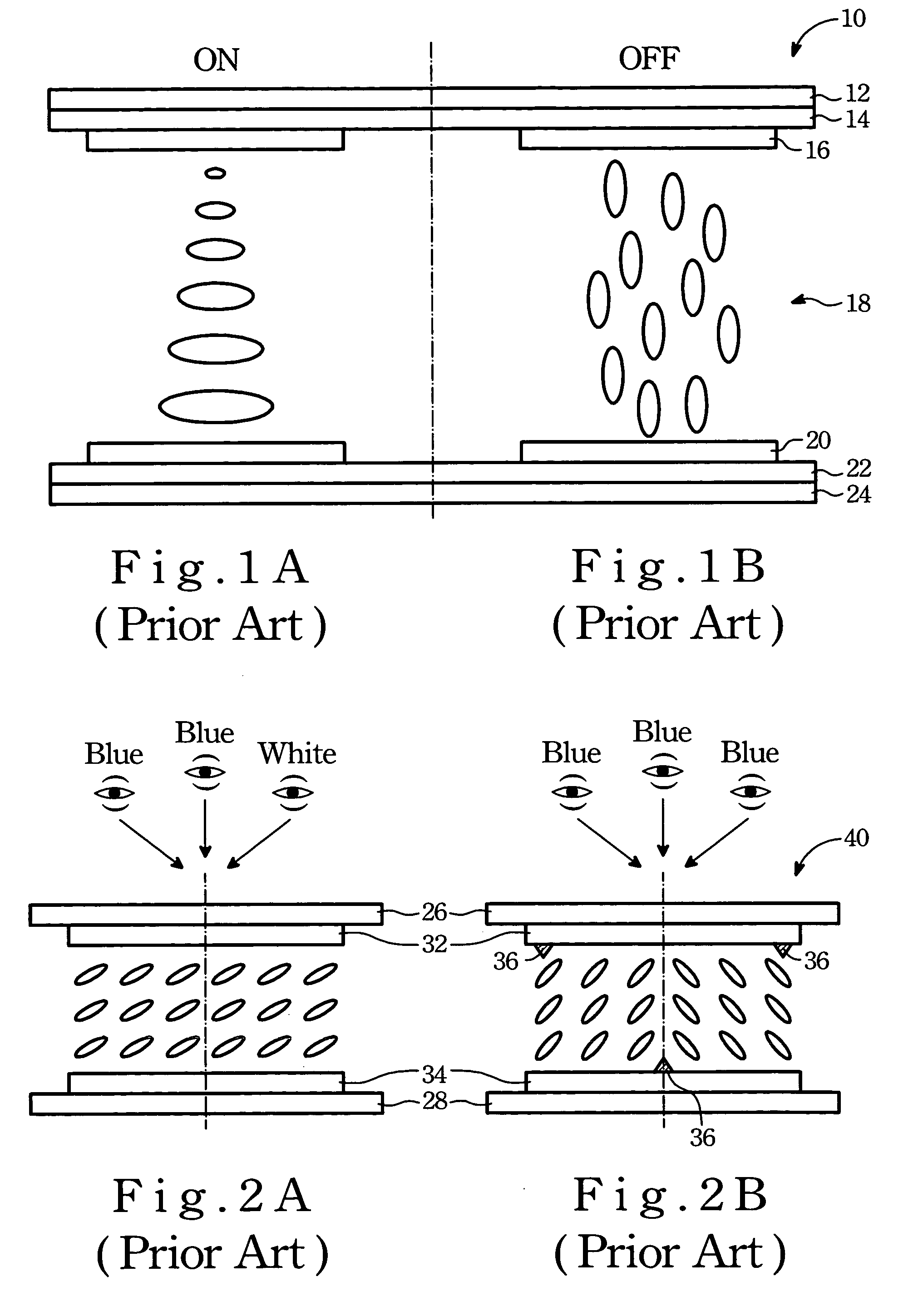
FIELD OF THE INVENTION[0001]The present invention relates to an LCD (Liquid Crystal Display) panel, more specifically to a transflective LCD panel of Vertical Alignment mode which is constructed in such a manner to provide uniform brightness throughout the entire length of the LCD panel.BACKGROUND OF THE INVENTION[0002]Referring to FIG. 1A, a conventional transflective LCD panel 10 of MTN (Mixed Twisted Nematic) mode is shown to include an upper polarizer 12, an upper glass substrate 14, an upper electrode 16, a liquid crystal layer 18, a lower electrode 20, a lower glass substrate 22 and a lower polarizer 24. When the transistor in the LCD panel 10 is switched on (i.e. when a voltage is applied onto opposite ends 16, 20 of the liquid crystal layer 18), an electric field will be induced, and extends parallelly to the upper and lower electrodes 16, 20. Since the phase difference between the upper and lower polarizers 12, 24 is 90°, the light beams passing through the lower polarizer ...

Claims


Application Information

Patent Timeline
Patent Type & Authority Patents(United States)
IPC IPC(8): G02F1/29G02F1/335H01L21/00H01L33/00G02F1/1333H01L27/146
CPCG02F1/133371H01L27/14621G02F2203/09
Inventor WU, YANG-EN
Owner AU OPTRONICS CORP
Features
  • R&D
  • Intellectual Property
  • Life Sciences
  • Materials
  • Tech Scout
  • Unparalleled Data Quality
  • Higher Quality Content
  • 60% Fewer Hallucinations
Learn More