Optical information medium having high resolution beyond a diffraction limit and reading method

a technology of optical information and reading method, which is applied in the direction of optical recording/reproducing/erasing method, mechanical recording, instruments, etc., can solve the problem of low carrier-to-noise ratio, unreadable level, and medium, however, inpractical, etc. problem, to achieve the effect of minimizing the dependence of a readout power

Inactive Publication Date: 2005-11-15
TDK CORPARATION
View PDF31 Cites 68 Cited by
  • Summary
  • Abstract
  • Description
  • Claims
  • Application Information

AI Technical Summary

Benefits of technology

[0011]An object of the invention is to provide an optical information medium which enables reading at a high resolution beyond the diffraction limit and minimizes the dependency of a readout power on a linear velocity. Another object is to provide a method for reading the information recorded in the optical information medium.
[0015]a functional layer having a function of increasing a spatial resolution.

Problems solved by technology

However, if the track density or line density is too high relative to the beam spot of reading light, the carrier-to-noise (C / N) ratio lowers, eventually to a level where signals are unreadable.
This medium, however, is impractical in that after reading, the mask layer must be transformed back to amorphous.
This, in turn, requires a complex control system and hence, an expensive medium drive.
The heat mode media also suffer from the problem that reading characteristics degrade with the repetition of reading operation because the mask layer is prone to degradation by repetitive heating.
Also in the photon mode, the size of an optical aperture depends on the power of reading light, indicating that supply of an excessive power makes so large an optical aperture that super-resolution readout may become impossible.
That is, the photon mode media are rather incompatible with multi-wavelength reading.

Method used


Image

  • Optical information medium having high resolution beyond a diffraction limit and reading method
  • Optical information medium having high resolution beyond a diffraction limit and reading method
  • Optical information medium having high resolution beyond a diffraction limit and reading method

Examples


Embodiment Construction

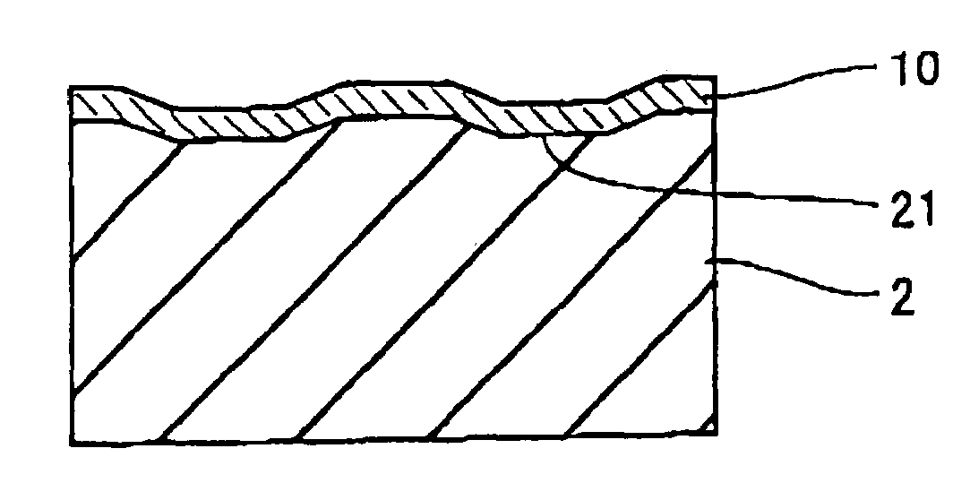
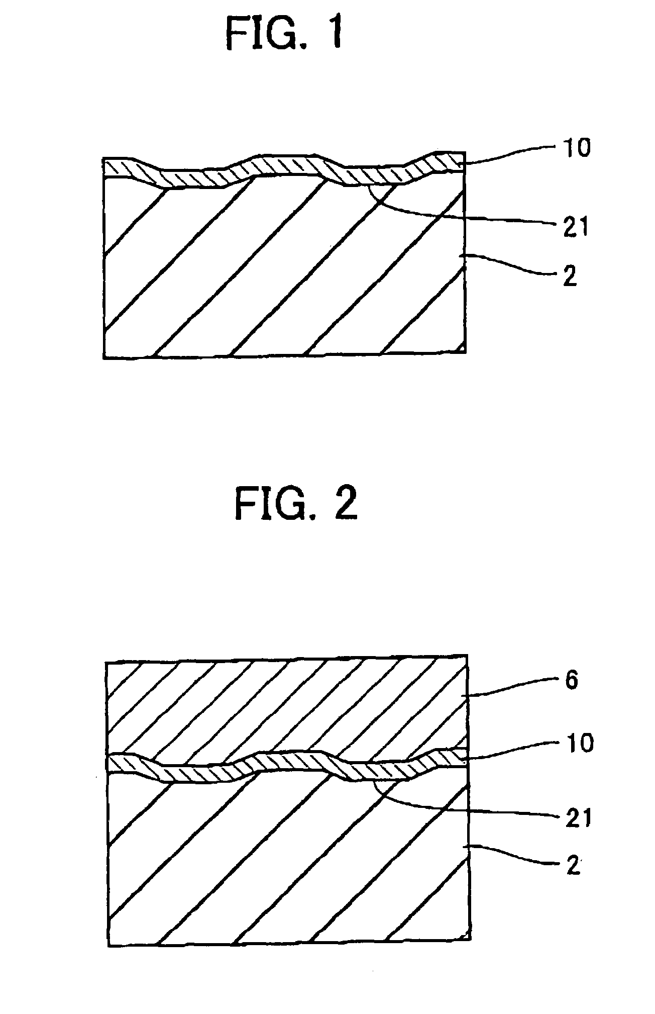
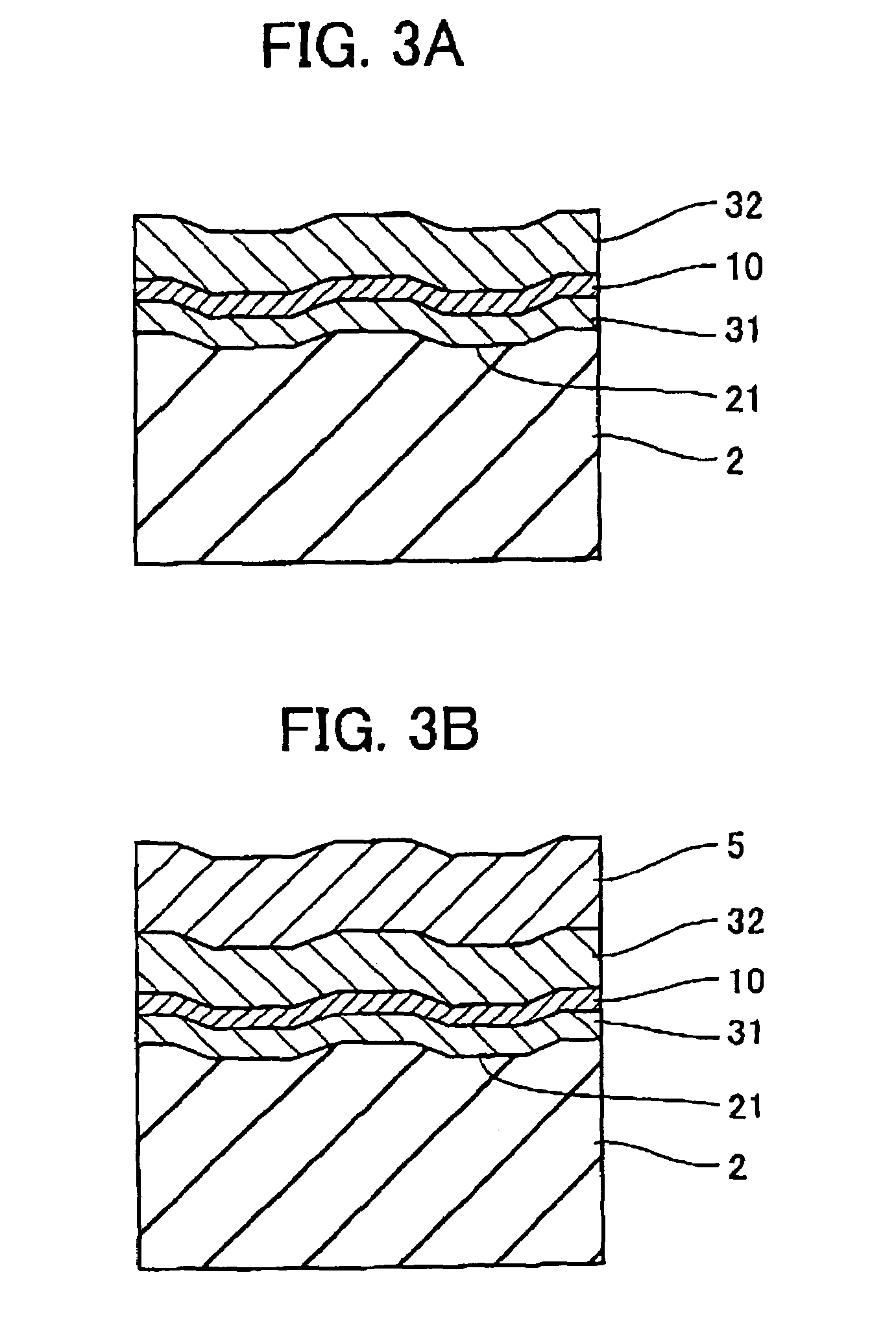
[0090]The optical information medium of the invention has an information bearing surface. The information bearing surface used herein means a region that has projections and depressions in the form of pits and / or grooves, a region where recorded marks can be formed, or a region that has projections and depressions and can form recorded marks. This suggests that the invention is applicable to both read-only media and optical recording media (write-once or rewritable media). In the read-only media, a substrate surface having pits formed therein constitutes the information bearing surface. In the optical recording media, the recording layer constitutes the information bearing surface. The recording layer may be any of a phase change layer, a layer based on an organic dye, and a layer based on another organic material or inorganic material. The recorded information may take the form of marks having a different optical constant (e.g., reflectance) from the surrounding, concave marks or c...


PUM

PropertyMeasurementUnit
thicknessaaaaaaaaaa
thicknessaaaaaaaaaa
thicknessaaaaaaaaaa

Abstract

In an optical information medium having an information bearing surface having projections and depressions and / or capable of forming recorded marks, a functional layer is added. The information borne on the information bearing surface can be read by using reading light of a wavelength longer than 4NA·PL wherein PL is the minimum size of the projections and depressions or the recorded marks and NA is the numerical aperture of a reading optical system, setting the power of the reading light within such a range that the functional layer does not change its complex index of refraction, and irradiating the reading light to the information bearing surface constructed by the functional layer or to the information bearing surface through the functional layer or to the functional layer through the information bearing surface. The medium enables reading at a high resolution beyond the diffraction limit.

Description

[0001]This invention relates to an optical information medium having a high recording density and a method for reading information in the medium.BACKGROUND OF THE INVENTION[0002]Optical information media include read-only optical discs such as compact discs, rewritable optical recording discs such as magneto-optical recording discs and phase change optical recording discs, and write-once optical recording discs using organic dyes as the recording material.[0003]In general, optical information media have a high information density as compared with magnetic recording media. The recent need to process a vast quantity of information as in images requires to further increase the recording density. The recording density per unit area can be increased either by narrowing the track pitch or by reducing the space or blank between recorded marks or between phase pits to increase a line density. However, if the track density or line density is too high relative to the beam spot of reading ligh...

Claims


Application Information

Patent Timeline
Patent Type & Authority Patents(United States)
IPC IPC(8): G11B7/005G11B7/24G11B7/00G11B7/24067G11B7/24085
CPCB82Y10/00G11B7/0052G11B7/24G11B7/24085
Inventor KIKUKAWA, TAKASHIUTSUNOMIYA, HAJIMESHINGAI, HIROSHIKATO, TATSUYA
Owner TDK CORPARATION
Why Eureka
Try Eureka