Check patentability & draft patents in minutes with Patsnap Eureka AI!

Distributed signaling system 7 (SS7) message routing gateway

a message routing and distribution signaling technology, applied in data switching networks, multiplex communication, digital transmission, etc., can solve the problems of high traffic volume, network outage, and ip networks that do not include the inherent reliability or stability of a conventional ss7 network

Inactive Publication Date: 2005-11-15
TEKELEC GLOBAL INC
View PDF143 Cites 31 Cited by
  • Summary
  • Abstract
  • Description
  • Claims
  • Application Information

AI Technical Summary

Benefits of technology

[0020]According to one aspect, the present invention includes a distributed SS7 gateway. The distributed SS7 gateway includes a plurality of distributed gateway routing elements. Each of the distributed gateway routing elements may be co-located with an SS7 node, such as an SSP or an SCP. Each of the distributed gateway routing elements performs an SS7 routing function, such as an MTP3 routing function. The distributed gateway routing elements route messages to other distributed gateway routing elements or to a translation services node for further processing. Such routing is similar to the internal routing performed by an SS7 STP or signaling gateway. As used herein, the phrase “signaling gateway” refers to a network node capable of routing telephony-related signaling messages between other network nodes and that is also capable of performing protocol translations for the signaling messages. However, because the functional components of the distributed gateway are co-located with network endpoints, rather than centrally located in a single node, the possibility of a complete network outage caused by failure of a single node is reduced.
[0023]Accordingly, it is an object of the present invention to provide a distributed message routing gateway that avoids at least some of the difficulties associated with conventional centralized routing nodes and with conventional IP telephony networks.

Problems solved by technology

Such disadvantages include expense due to processing requirements of centralized nodes, high-traffic volume at the centralized nodes, and possible network outage if one or more of the centralized nodes fails.
While IP networks provide a number of advantages, IP networks do not include the inherent reliability or stability of a conventional SS7 network.
As discussed above, the conventional SS7 network architecture includes centralized routing elements which are expensive, complex, and subject to high-traffic volumes.

Method used


Image

  • Distributed signaling system 7 (SS7) message routing gateway
  • Distributed signaling system 7 (SS7) message routing gateway
  • Distributed signaling system 7 (SS7) message routing gateway

Examples


Embodiment Construction

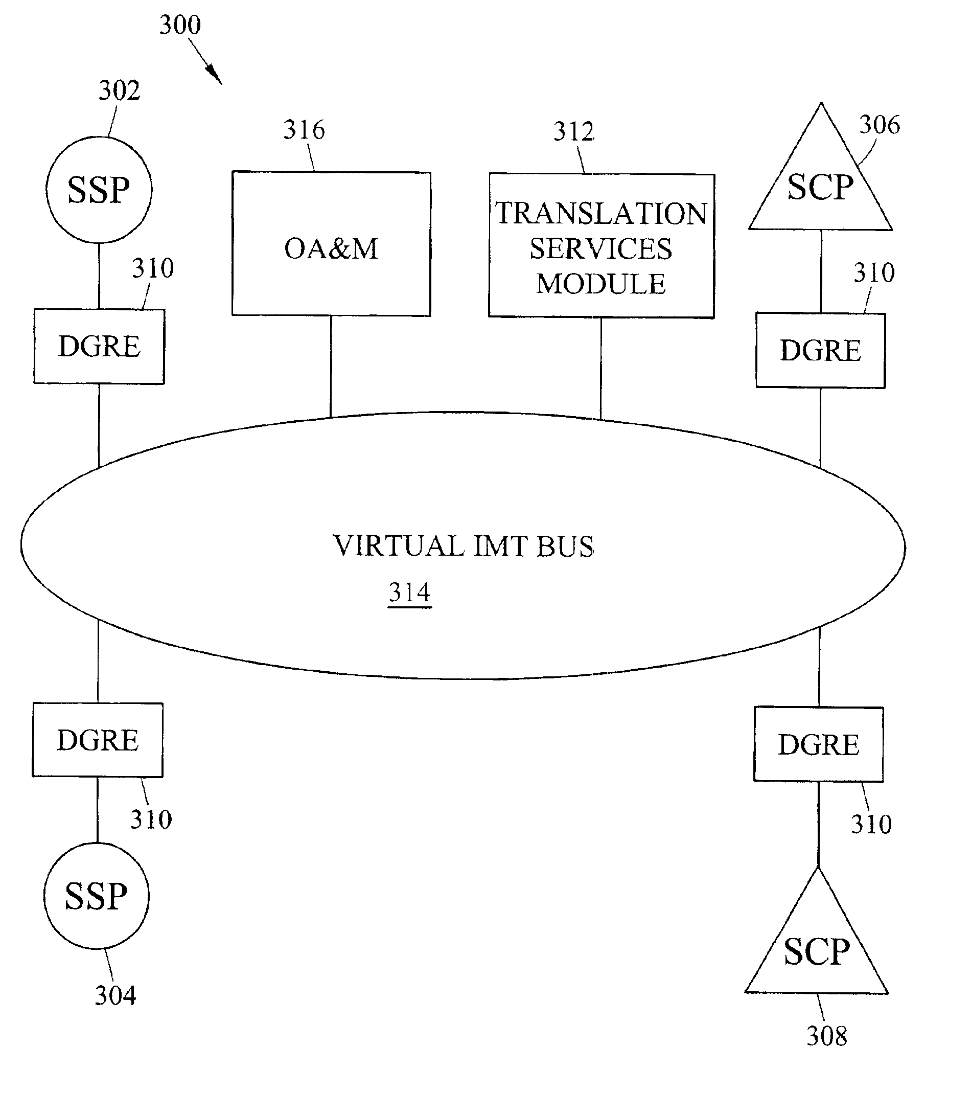
[0037]Rather than locating all of the SS7 routing architecture in a centralized network element, such as a signal transfer point or signaling gateway, embodiments of the present invention include a plurality of distributed gateway routing elements that are co-located with other SS7 network elements. The distributed gateway routing elements function collectively as a signal transfer point or signaling gateway. However, because the distributed gateway routing elements are not located together in a single location, the processing load on each element is reduced and the possibility of a complete network failure is reduced.

[0038]FIG. 3 is a block diagram of a communications network including a distributed gateway according to an embodiment of the present invention. Referring to FIG. 3, network 300 includes conventional SS7 network elements, such as SSPs 302 and 304 and SCPs or application servers 306 and 308. However, unlike a conventional SS7 network, network 300 does not include a conv...


PUM


Abstract

A distributed gateway includes distributed gateway routing elements co-located with SS7 network elements. Each distributed gateway routing element performs an SS7 routing function, such an MTP level 3 routing function. The distributed gateway routing elements communicate with each other over a virtual bus that guarantees quality of service for SS7 message packets. Accordingly, the distributed gateway routing elements set quality of service parameters in the SS7 message packets that are forwarded over the virtual bus.

Description

TECHNICAL FIELD[0001]The present invention relates to an SS7 message routing gateway. More particularly, the present invention relates to a distributed SS7 message routing gateway.BACKGROUND ART[0002]The conventional telecommunications network includes two distinct communication pathways or subnetworks—a voice network and a signaling network. These two networks function in a cooperative manner to facilitate a call between users. As implied by its name, the voice network handles the transmission of voice (or user data) information between users. The signaling network has a number of responsibilities, which include call setup, call teardown, and database access features. In simple terms, the signaling network facilitates the dynamic linking together of a number of discrete voice-type communication circuits, such that a voice-type connection is established between the calling and called party. These functions are generically referred to as call setup and call teardown. Additionally, th...

Claims


Application Information

Patent Timeline
IPC IPC(8): H04Q3/00
CPCH04Q3/0025H04Q3/0045
Inventor TINSLEY, ROBERT JOHNMARSICO, PETER JOSEPHSMITH, LEE BARFIELDLONG, VIRGIL ELMERHUNT, GREGORY ALLEN
Owner TEKELEC GLOBAL INC
Features
  • R&D
  • Intellectual Property
  • Life Sciences
  • Materials
  • Tech Scout
  • Unparalleled Data Quality
  • Higher Quality Content
  • 60% Fewer Hallucinations
Learn More