Method and system for displaying data in a second display area

a technology of a second display area and a method and a system, which is applied in the direction of program control, multi-programming arrangements, instruments, etc., can solve the problems of requiring a significant amount of time relative to the presentation of a scanned line of data, modern monitors have become much faster in their retrace speeds, and a significant amount of time when the electron gun cannot be blanked, so as to increase the accessible area of the display. , the effect o

Inactive Publication Date: 2005-11-15
OSTENDO TECH INC
View PDF102 Cites 30 Cited by
  • Summary
  • Abstract
  • Description
  • Claims
  • Application Information

AI Technical Summary

Benefits of technology

[0007]When the electron gun in a CRT retraces to the left of the screen or the top of the screen, it requires a significant amount of time relative to the presentation of a scanned line of data. During the retrace, the electron gun is turned off (“blanked”). If the blanking time required for the retrace is equal to the amount of time available, there is no usable overscan. However, modern monitors have become much faster in their retrace speeds, leaving a significant amount of time when the electron gun need not be blanked, allowing a displayable border. In the prior art, although the border is usually “black” (the gun is turned off), it is well-known to specify that the border shall be given any one of six colors. Standard BIOS allows a specification of this color. The desired color is simply specified in one of the registers for the video controller. No data for this color is stored in the buffer of video memory for the display. This invention establishes an additional video buffer for the border and allows his buffer to be written with display data like the regular display buffer. The display area is thereby expanded, on one or more edges, to provide a visible area previously invisible. The pixels within this newly visible area of the display are made accessible to programs though an application programming interface (API) component of this invention. A program incorporating a graphical user interface may be displayed in the previously blanked area of the display, functionally increasing the accessible area of the display without hardware modification.

Problems solved by technology

When the electron gun in a CRT retraces to the left of the screen or the top of the screen, it requires a significant amount of time relative to the presentation of a scanned line of data.
However, modern monitors have become much faster in their retrace speeds, leaving a significant amount of time when the electron gun need not be blanked, allowing a displayable border.

Method used


Image

  • Method and system for displaying data in a second display area
  • Method and system for displaying data in a second display area
  • Method and system for displaying data in a second display area

Examples


Embodiment Construction

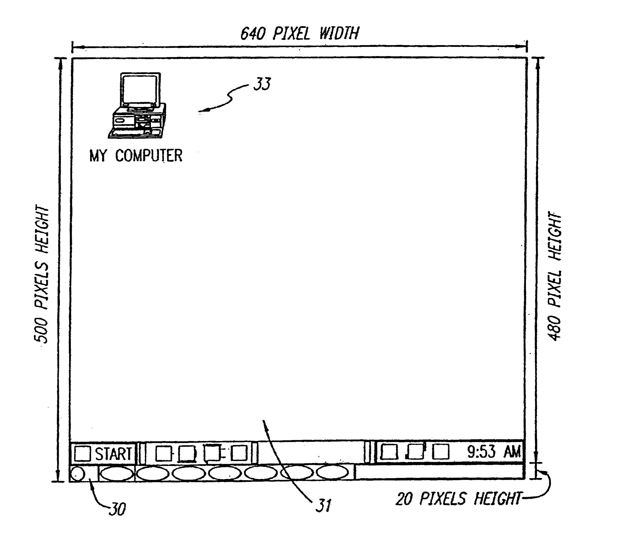
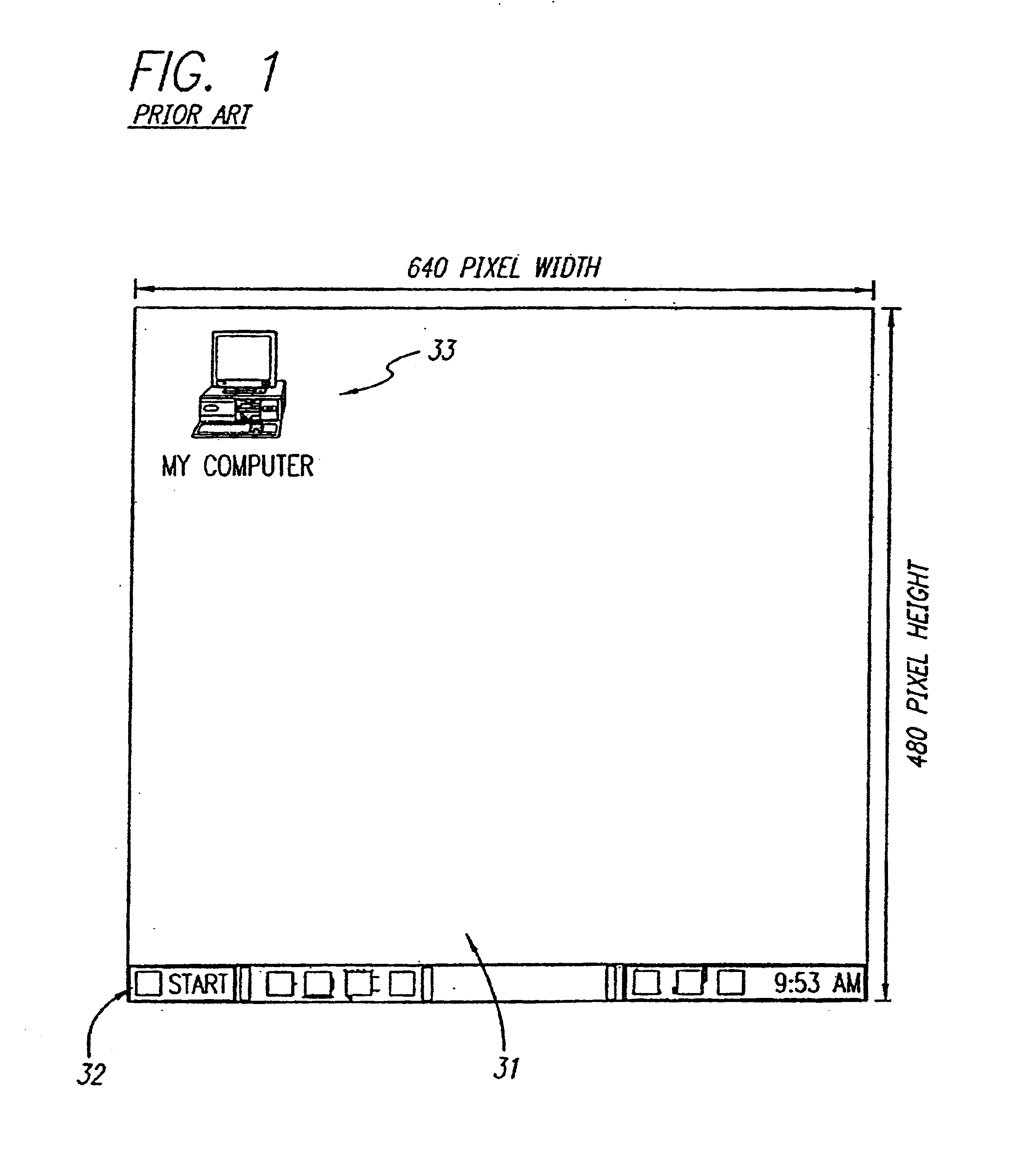
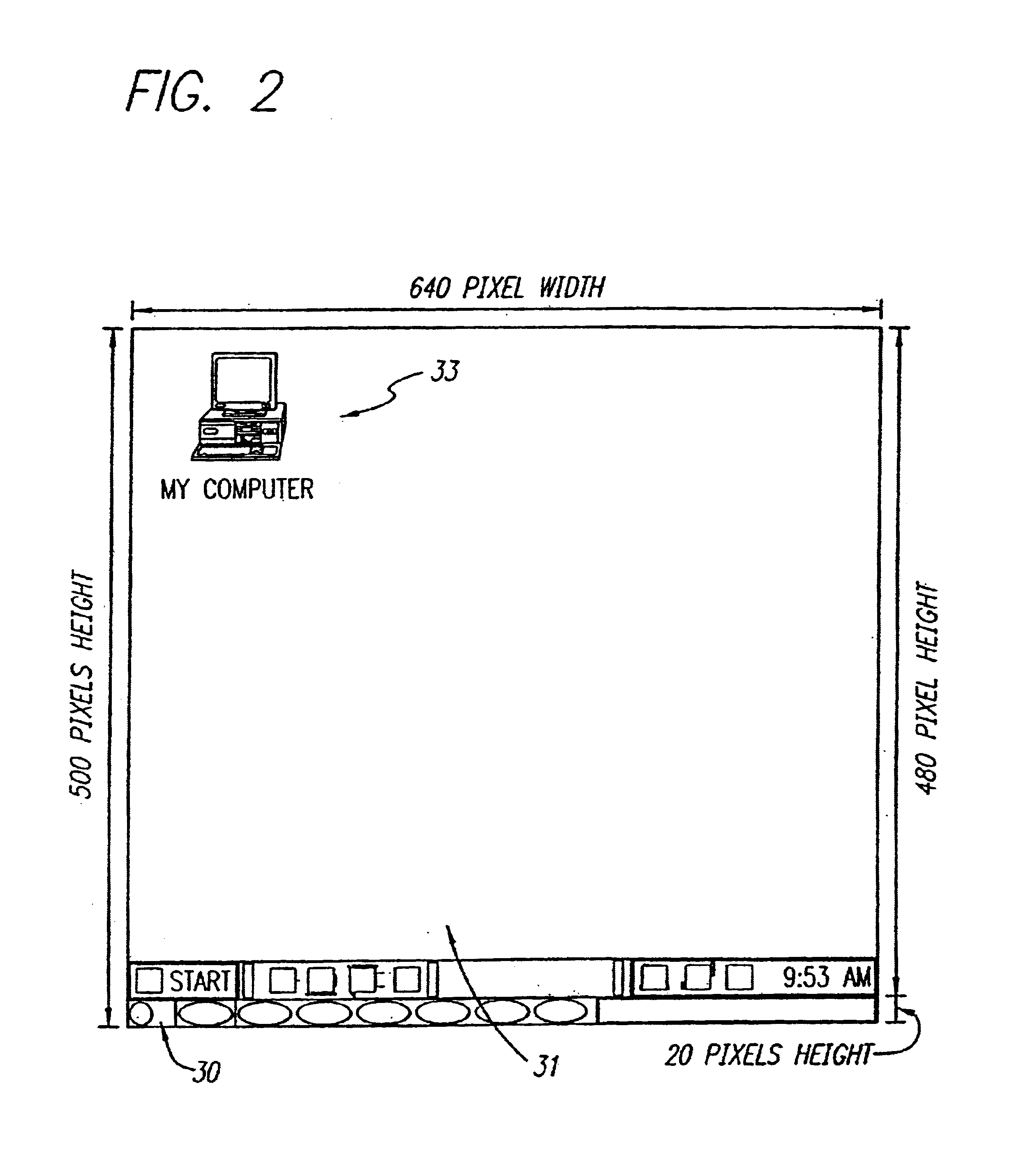
[0018]Generally speaking, the present invention discloses a programming mechanism and interface in a computer system which provides access and visibility to a portion of the monitor display normally ignored and inaccessible (hereinafter “overscan area”). FIG. 1 shows a standard prior art display desktop running Microsoft Windows95™. Within the desktop 31 are the taskbar 32 and desktop icons 33. In the preferred embodiment, a graphical user interface image is painted onto one or more of the sides of the overscan area as shown in FIGS. 2 and 3. FIGS. 2 and 3 show depictions of a SuperVGA display with the addition of a graphical bar user interface displayed in the overscan area. The overscan user interface bar 30 is defined to reside outside the borders of the “desktop” display area 31. In FIG. 2, the display is modified to include a graphical user interface 30 in a bar 20-pixels high below the bottom edge. In FIG. 3, the display is modified to include a graphical user interface in fou...


PUM


Abstract

A method for creating and accessing a graphical user interface in the overscan area outside the area of the display normally visible to users of the common operating systems. This normal display area is generally known as the “desktop”. The desktop serves as the graphical user interface to the operating system. The desktop displays images representing documents and applications available to the user (icons). The desktop is restricted in the common environments to a predetermined set of resolutions (e.g., 640×480, 800×600, 1024×768) as defined by VGA and SuperVGA standards. Displayable borders outside this area are the overscan.

Description

[0001]This invention relates to computer user interface displays and the use of the overscan border to present a user interface beyond the perimeter of a standard user interface display.BACKGROUND OF THE INVENTION[0002]There was a time when the most popular operating system for personal computers (DOS) did not include a graphical user interface. Any company could create a “menu” or “shell” which would be the first program launched upon starting the computer and which would present options to the user for launching and managing various applications. Although graphics programming was difficult in the DOS environment, some companies even created graphical user interfaces which could then launch other programs.[0003]Microsoft Corporation of Redmond, Wash., introduced such a graphical user interface for launching applications which it called “Windows”. The first three versions of Windows were merely applications which ran under DOS and could be one of numerous items to be selected from a...

Claims


Application Information

Patent Timeline
Patent Type & Authority Patents(United States)
IPC IPC(8): G09G5/14G09G1/16G06F9/44
CPCG06F3/14G06F9/4443G09G1/16G09G5/14G09G2320/08G06F9/451
Inventor NASON, D. DAVIDO'ROURKE, THOMAS C.CAMPBELL, J. SCOTT
Owner OSTENDO TECH INC
Why Eureka
Try Eureka