
Wind turbine rotor blade comprising one or more means secured to the blade for changing the profile thereof depending on the atmospheric temperature

a technology of wind turbines and rotor blades, which is applied in the direction of propellers, propulsive elements, water-acting propulsive elements, etc., can solve the problems of stall-controlled wind turbines not reaching the prescribed maximum power output, turbines may overproduce power, and the lift is influenced by the air density. to achieve the effect of increasing or reducing the maximum lift power

Inactive Publication Date: 2005-11-22
LM GLASSFIBER
View PDF16 Cites 30 Cited by
  • Summary
  • Abstract
  • Description
  • Claims
  • Application Information

AI Technical Summary

Benefits of technology

[0008]According to a preferred embodiment the laminate comprises a first and a second layer of a composite material. A means of such materials is advantageous in that it is not electrically conducting and thus does not attract lightning.
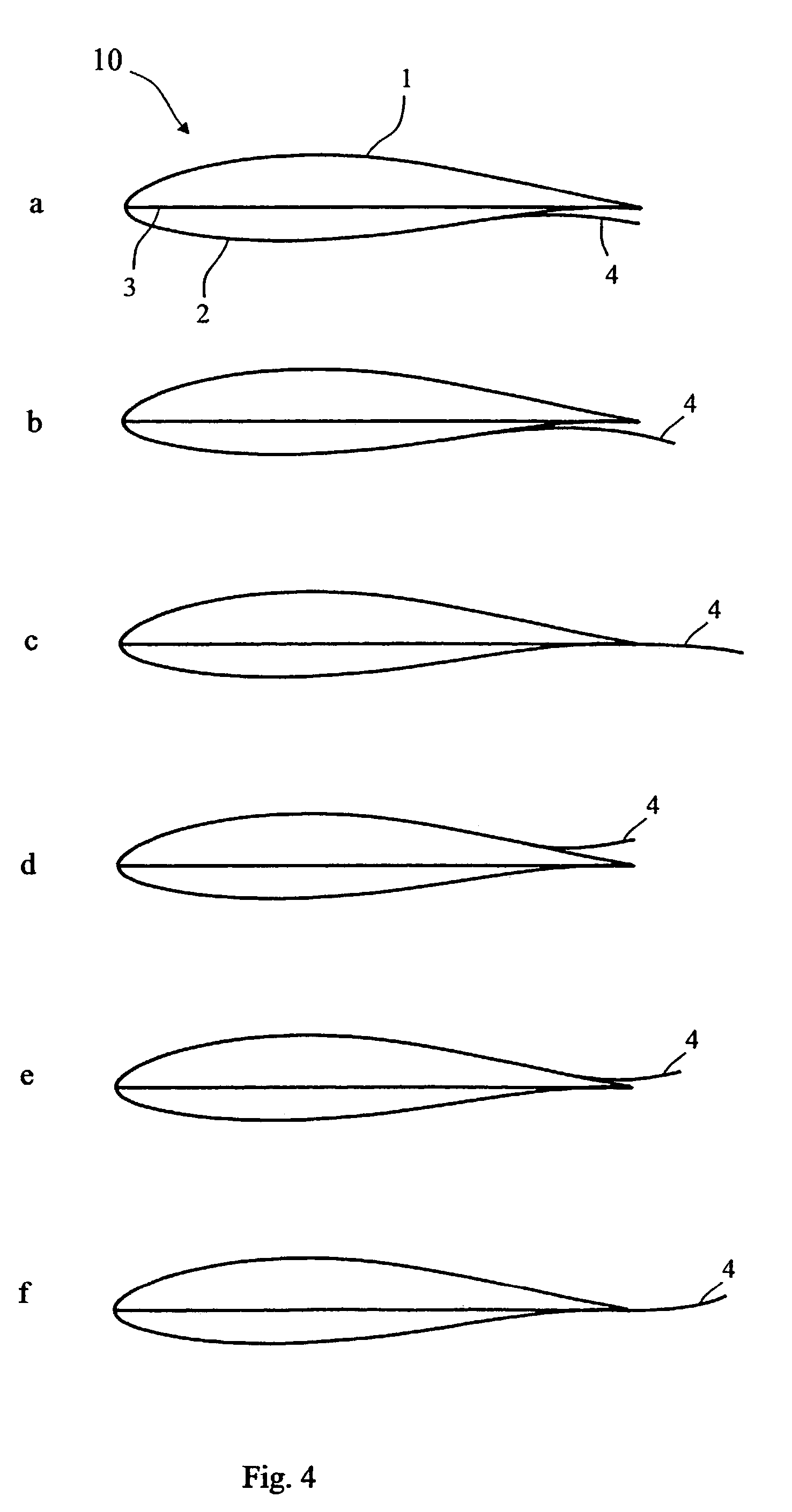
[0013]According to a preferred embodiment of the invention the means may be a flap mounted adjacent the trailing edge of the rotor blade. It is easy to after the profile by means of such a laminated flap.
[0017]Instead of using one long means, it may be advantageous to provide the blade with several separate means arranged end to end in the longitudinal direction of the blade so as to reduce any problems arising in connection with the temperature-dependent expansion / contraction of the means in the longitudinal direction.

Problems solved by technology

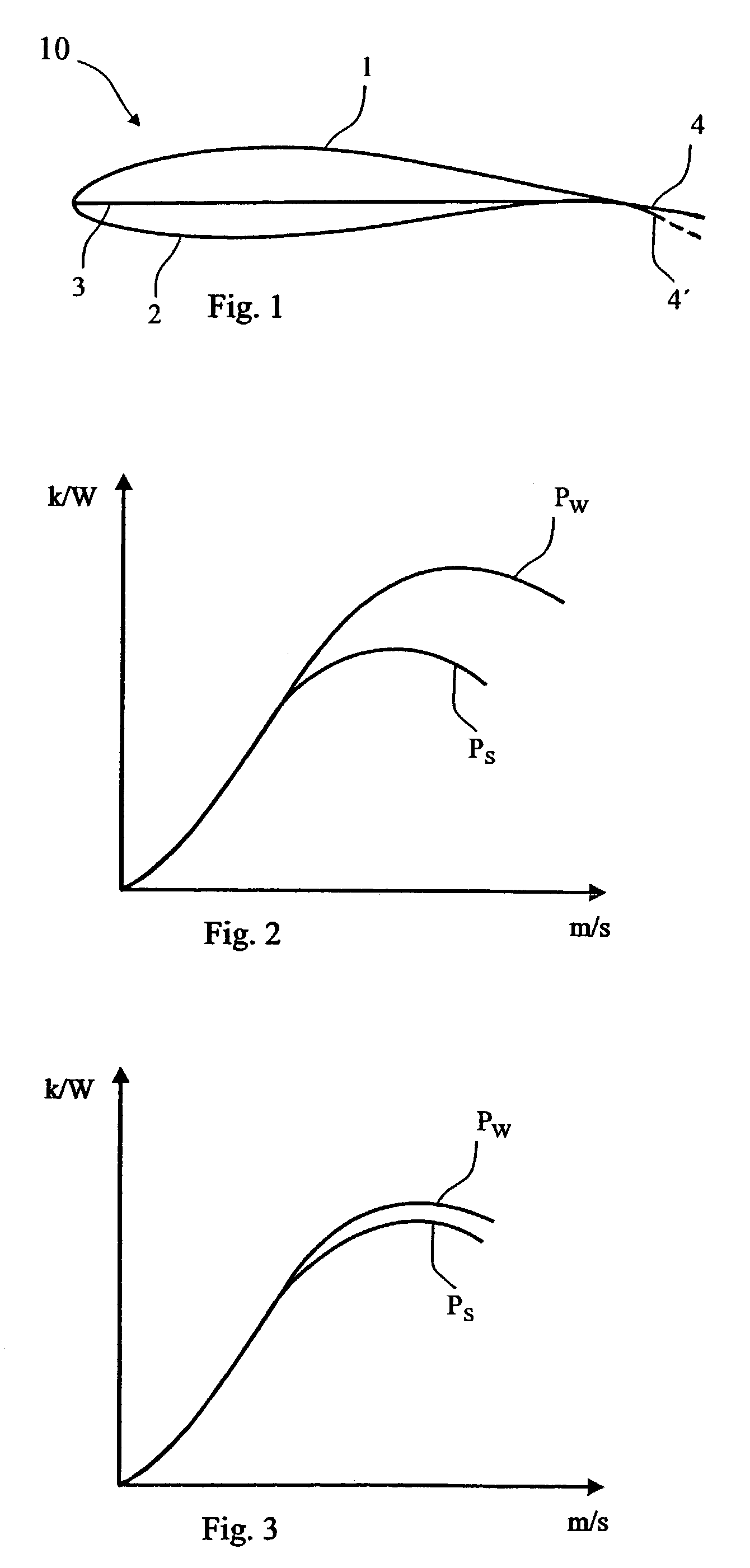
Stall control renders a simple and reliable adjustment of the turbine, but is encumbered by the drawback that the lift varies according to the air density.
At high temperatures and thus low air density, a stall-controlled wind turbine typically does not reach the prescribed maximum power output.
Conversely, during winter, where the temperature is low, the wind turbine may overproduce power, whereby the gear box or the generator may be also overloaded.
One drawback of the blade according to the WO publication is that the element may cause sudden stall over the entire profile and thus cause a drastic reduction of the maximum power output.

Method used


Image

  • Wind turbine rotor blade comprising one or more means secured to the blade for changing the profile thereof depending on the atmospheric temperature
  • Wind turbine rotor blade comprising one or more means secured to the blade for changing the profile thereof depending on the atmospheric temperature
  • Wind turbine rotor blade comprising one or more means secured to the blade for changing the profile thereof depending on the atmospheric temperature

Examples


Embodiment Construction

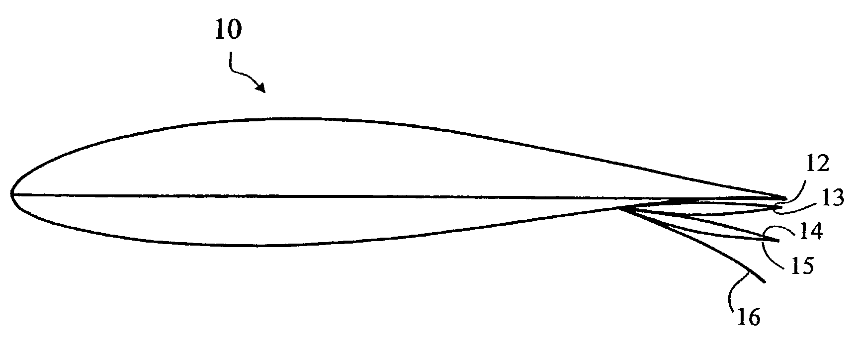
[0027]According to the invention the blade profile 10 shown in FIG. 1 is provided with a flap 4 at its trailing edge. The aerodynamic pressure side of the blade profile is denoted by the reference numeral 2 and the suction side of the blade profile 10 facing the wind turbine tower on upwind turbines is denoted by the reference numeral 1. The width of the flap 4 shown in FIG. 1 is 10% of the chord 3 of the profile. The flap 4 is illustrated by means of a continuous line at a first temperature and by means of a dash line at a second higher temperature. The shown flap 4 may be made of a bimetal formed of two bonded and rolled metal layers with differing thermal expansion coefficients. A flap of bimetal may optionally be used as a conductor for conducting lightning down into the ground. The flap is, however, preferably made of a laminate of composite materials, eg a layer of fibreglass-reinforced epoxy, in which the fibres extend in the transverse direction of the flap and thus of the b...


PUM


Abstract

A wind turbine rotor blade (10) comprising one or more means (4) secured to the blade (10) for changing the profile thereof depending on the atmospheric temperature. The means comprises at least one laminate having at least two layers of materials with differing thermal expansion coefficients.

Description

[0001]This application is a continuation of PCT / DK01 / 00423, filed Jun. 18, 2001, which claimed priority to Denmark Patent Application No. DK PA 2000 00946, filed June 19, 2000.TECHNICAL FIELD[0002]The invention relates to a wind turbine rotor blade comprising one or more means secured to the blade for changing the profile thereof depending on the atmospheric temperature.BACKGROUND ART[0003]Stall-controlled and active stall-controlled wind turbines are designed to operate at a substantially fixed speed of rotation, ie the blade rotates at the same speed irrespective of the wind speed. At high wind speeds, the power output has to be limited so as not to overload the generator. Pitch control, active stall control or (passive) stall control may be used for this purpose. At pitch control and active stall control the blades are mounted such on the hub that they are able to turn around their longitudinal axis. The rotor blades may thus be continuously adjusted to provide the lift rendering...

Claims


Application Information

Patent Timeline
IPC IPC(8): B63H1/26B63H1/00F01D5/14F03D1/00F03D7/02F03D7/04F03D11/00F03D1/06F03D7/00
CPCF01D5/147F01D5/148F03D1/0641F03D7/0232F05B2240/31Y02E10/721Y02E10/723Y02E10/72
Inventor GRABAU, PETERFRYDENDAL, IB
Owner LM GLASSFIBER
Learn More