Buffing head and method for reconditioning an optical disc

a technology of optical discs and reconditioning heads, which is applied in the direction of photosensitive materials, carpet cleaners, instruments, etc., can solve the problems of preventing the player from reading the data correctly, affecting the playback quality and visual appearance of optical discs, and many used discs cannot be resold. , to achieve the effect of facilitating use, restoring both the playback quality and the visual appearance of optical discs, and effective scratch removal

Inactive Publication Date: 2005-11-22
AZURADISC
View PDF29 Cites 6 Cited by
  • Summary
  • Abstract
  • Description
  • Claims
  • Application Information

AI Technical Summary

Benefits of technology

[0012]Accordingly, it is an advantage of the present invention that a buffing head and a method are provided that restore both the playback quality and the visual appearance of an optical disc.
[0013]It is another advantage of the present invention that a buffing head and method are provided that adequately control buffing parameters to yield effective scratch removal from the protective surface of the disc.
[0014]Another advantage of the present invention is that a buffing head and method are provided that facilitate the use, and mitigates the waste, of cooling liquid.
[0015]Yet another advantage of the present invention is that the buffing head is readily expandable between consumer and commercial / industrial applications.
[0016]The above and other advantages of the present invention are carried out in one form by a buffing head for reconditioning a work surface of an optical disc. The buffing head includes a rotary element for rotating the disc at a first speed, and a buffing element configured to contact the work surface so that rotation of the disc enables corresponding movement of the buffing element. A restrictor is in communication with the buffing element for restricting movement of the buffing element such that the buffing element moves at a second speed to recondition the work surface, the second speed being slower than the first speed.
[0017]The above and other advantages of the present invention are carried out in another form by a buffing head for reconditioning a work surface of an optical disc. The buffing head includes a rotary element for rotating the disc. A buffing element is configured to contact the work surface so that rotation of the disc enables corresponding movement of the buffing element. A well surrounds the buffing element and contains a fluid. Movement of the buffing element causes the buffing element to be immersed into the fluid and to be returned into contact with the work surface.

Problems solved by technology

Damage or surface imperfections located on the transparent protective surface can interfere with the laser beam before it reaches the data layer.
Although modern playback devices include error correction techniques, this interference can prevent the player from reading the data correctly, or at all, even though the data layer itself is undamaged.
However, many used discs cannot be resold because imperfections in the protective surface render them unplayable or visually unappealing.
However, if the relative speed is inadequately controlled, i.e., the relative speed is too great, cooling liquid and polishing compound can be simply flung off of the optical disc.
This leads to waste of the cooling liquid and / or polishing compound, as well as ineffective heat absorption and buffing.
Such devices are undesirably costly and have a higher probability of component failure due to the complexity of the equipment.
The pressure between the buffing element and the optical disc also affects the effectiveness of the reconditioning process.
If the pressure is too great, too much material may be removed, which can damage the underlying data track and / or cause excessive heat build up.
Conversely, if the pressure is too low, reconditioning time becomes undesirably long and less cost effective, especially in the commercial market.
Yet another problem associated with pressure is the effect of uneven pressure between the contact surface of the buffing element and the protective surface of the optical disc.
This uneven pressure can result in non-uniform reconditioning of the protective surface.
This non-uniform reconditioning may cause laser beam focus problems, vibrations, and signal distortion during playback.
In order to control the pressure between the buffing element and the protective surface of the optical disc, many reconditioning devices employ complex and costly mechanisms that provide motion in multiple planes.
Again, such devices are undesirably costly and have a higher probability of component failure due the complexity of the equipment.
Unfortunately, while this method may effectively repair the protective coating of a single digital disc, it is so time consuming that it is impractical for repairing a large number of discs.
Furthermore, the complex machinery is too costly for the consumer market.
Moreover, debris from the coarse buffing stage can contaminate the protective surface of the optical disc when performing the fine buffing, thus compromising the effectiveness of the finer buffing stages.

Method used


Image

  • Buffing head and method for reconditioning an optical disc
  • Buffing head and method for reconditioning an optical disc
  • Buffing head and method for reconditioning an optical disc

Examples


Embodiment Construction

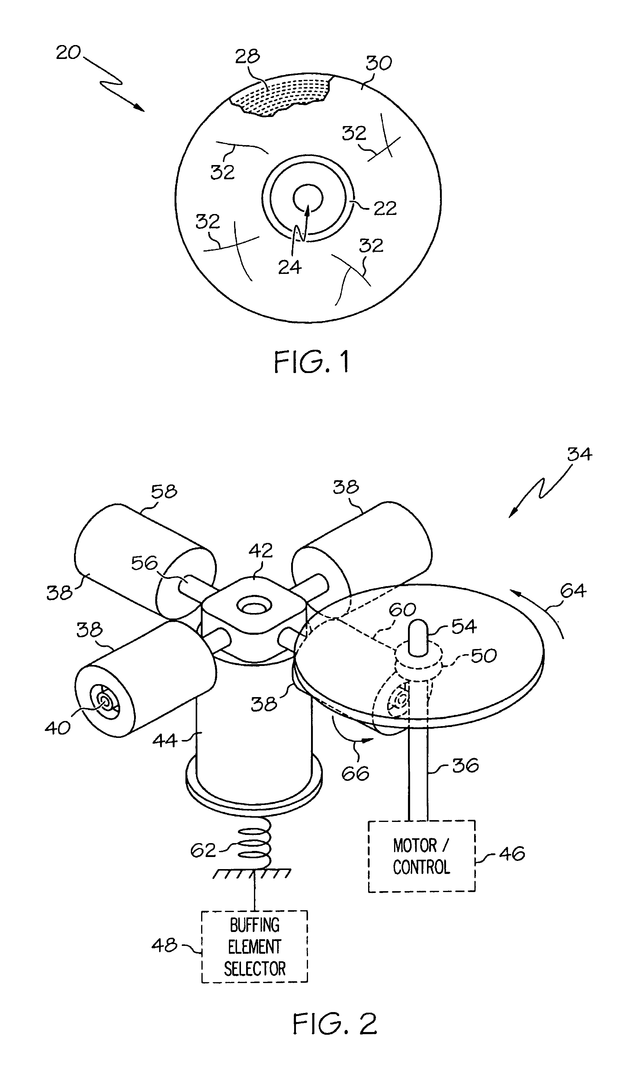
[0029]FIG. 1 shows a diagram of an optical disc 20. Optical disc 20 may be a compact disc, digital versatile disc (DVDs), CD-ROM, recordable CD (CD-R), re-writable CD (CD-RW), a game disc, and the like. Optical disc 20 generally includes a center section, or clamping area 22, located about a center hole 24 of disc 20. Surrounding clamping area 22 is a narrow text band 26 typically used to identify the manufacturer. Clamping area 22 and text band 26 do not contain encoded data. A data layer 28 lies outside of text band 26. Data layer 28 is arranged in spiral tracks and is covered by a protective surface 30. Disc 20 is shown with a portion of protective surface 30 removed to show the underlying spiral arranged data layer 28. In addition, disc 20 is shown with surface imperfections, such as, scratches 32, in protective surface 30 that render disc 20 unplayable or visually unappealing.

[0030]In general, when disc 20 is undamaged, the laser beam of the disc playback equipment enters disc ...


PUM

PropertyMeasurementUnit
work surfaceaaaaaaaaaa
speedaaaaaaaaaa
movementaaaaaaaaaa

Abstract

A buffing head (34) includes a rotary element (36) for retaining an optical disc (20) and causing the disc (20) to rotate at a first speed. A buffing element (38) contacts a work surface (30) of the optical disc (20), and rotation of the disc (20) enables corresponding movement of the buffing element (38). A restrictor (40), in communication with the buffing element (38), restricts movement of the buffing element (38) so that the buffing element (38) moves at a second speed to recondition the work surface (30), the second speed being slower than the first speed. The buffing head (34) further includes a well (86) surrounding the buffing element (38) and containing a fluid (88). Movement of the buffing element (38) causes the buffing element (38) to be immersed into the fluid (88) and to be returned into contact with the work surface (30).

Description

TECHNICAL FIELD OF THE INVENTION[0001]The present invention relates generally to optically-read digital recording discs. More specifically, the present invention relates to reconditioning the protective surface of optically-read digital recording discs.BACKGROUND OF THE INVENTION[0002]Optical-read digital recording discs, including compact discs (CDs), digital versatile discs (DVDs), CD-ROMs, recordable CDs (CD-Rs), re-writable CDs (CD-RWs), game discs, and the like, are widely used to store different types of information. Such optical discs may be formatted for use with audio, video, game, or computer equipment that reads the data recorded on the discs. The technology associated with optical discs and digital playback equipment is well known to those skilled in the art. Basically, digital information is encoded and arranged in spiral data tracks within the disc beneath an optically transparent protective layer, or surface, of plastic. A laser beam reads the digital information duri...

Claims


Application Information

Patent Timeline
Patent Type & Authority Patents(United States)
IPC IPC(8): B24B29/00B24B27/00B24B29/02B24D13/00B24D13/14
CPCB24B27/0061B24B29/02B24D13/145
Inventor BAUER, JASONSHEKHEL, ALEXANDER
Owner AZURADISC
Why Eureka
Try Eureka