
Counterweighted golf club

a golf club and weight technology, applied in golf clubs, racket sports, gymnastics, etc., can solve the problems of inability to achieve the effect of reducing the impact force, so as to improve the impact force and improve the golfer's accuracy. , the effect of increasing the moment of inertia

Inactive Publication Date: 2005-11-22
BLOOM JR JAMES PIERCE
View PDF45 Cites 33 Cited by
  • Summary
  • Abstract
  • Description
  • Claims
  • Application Information

AI Technical Summary

Benefits of technology

[0017]It is an object and advantage of the present invention to provide a golf club that increases a golfer's accuracy and therefore improves golf scores.
[0018]A further object and advantage of the present invention is to place the center of gravity of the entire golf club within the grip and therefore within a golfer's gripping hands as he or she swings the club.
[0019]Another object and advantage of the present invention is to substantially increase the moment of inertia of the golf club about the axis defined by its shaft and therefore minimize the tendency of the club to twist if the golf ball is struck away from the center of the club face and to insulate the stroke from the effects of unintentional and external forces.
[0020]A still further object and advantage of the present invention is to effectively enlarge the sweet spot on the club face.
[0021]Yet another object and advantage of the present invention is to provide a golf club that maintains a state of neutral equilibrium, and therefore eliminates the bottom-heavy feel of the golf club at address, making the club head feel seemingly weightless as a golfer addresses the ball.
[0022]A further object and advantage of the present invention is to provide a gripping surface with increased ergonomics, which will promote a palm grip by both of the golfer's hands, which will decrease the golfer's tendency to tightly clench the club, and which will result in a light grip pressure.

Problems solved by technology

However, because the hands perform similar functions in a putting stroke, this small diameter grip is unnecessary.
Compared to these clubs, the putter carries out its function at a near stand-still, and such a primary emphasis on lightweight design would be misplaced.
Unfortunately, with a typical prior art putter, there are many forces acting on the putter in several different directions during the putting stroke.
This is no easy task.
An imperfect putting stroke may result in the club head (or blade) being struck off-center, which may cause the putter to twist in the golfer's hands and lose the all-important line.
Many of these designs use sophisticated and complex heel-toe or perimeter weighting systems and exotic and extremely heavy materials such as tungsten or special alloys.
The added weight moves the center of gravity up the club shaft towards the grip end of the club marginally, but to the inventor's knowledge no design that adds weight exclusively within the inside of a standard diameter club shaft can move the center of gravity of the putter so far as to locate it actually in the region of the club gripped by a golfer, while maintaining a conventional length club.
Consequently, the club head's weight causes a large, hard to control, output during the swing.
Further, an object may be in unstable equilibrium or in neutral equilibrium.
When an object is in unstable equilibrium, any displacement away from its equilibrium position will cause the object to tend further away from equilibrium.
If in the physical system of a golfer gripping a putter, the fulcrum is taken to be the normal pivot at the golfer's hands on the handle, a typical prior art putter is in unstable equilibrium.
Thus the inherent difficulties described above.
In addition to its instability and relatively small moment of inertia, the small diameter grip of a typical prior art putter tends to place the control of the putting stroke in the small, twitchy muscles of the hands and forearms.
The small diameter grip promotes much more of a finger grip, rather than a preferred palm grip for putting, which may result in the golfer clenching the club with the fingers and placing a heavy load on the small finger muscles.
Another problem caused by the bottom-heavy design of most prior art putters is that as the putter is swung back, the handle end tends to move ahead of the club head.
This non-uniform movement causes the imaginary line formed by shaft up through the arms to the shoulders to be broken at the hands during the swing, effecting a chaotic double pendulum.
The problem is exacerbated by the fact that the pendulum's bob is the putter's head.
This double-pendulum effect is undesirable in light of the commonly preferred method of swinging a putter, which is to pivot only at the shoulders, keeping the wrists locked, thus simulating a simple single-pendulum swing.
Moreover, the typically circular cross-section of most prior art grip designs does not assist the golfer in hand placement.
Simply put, each of the preceding characteristics of conventional putter design impairs the overall ergonomics of the club.
Finally, many commercially successful putters have complex and sophisticated heel-toe or perimeter-weighting systems and use exotic materials.
These exotic materials, such as elastomer, tungsten or special alloys, and the materials science research involved in developing them, make putters expensive.
In addition, complex designs may require special manufacturing processes, driving up costs even more.

Method used


Image

  • Counterweighted golf club
  • Counterweighted golf club
  • Counterweighted golf club

Examples


Embodiment Construction

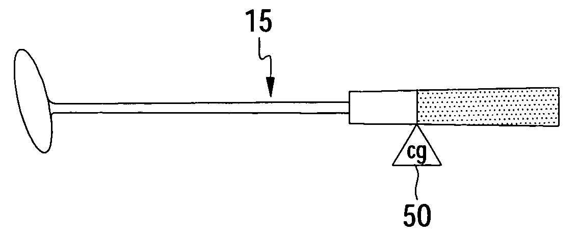
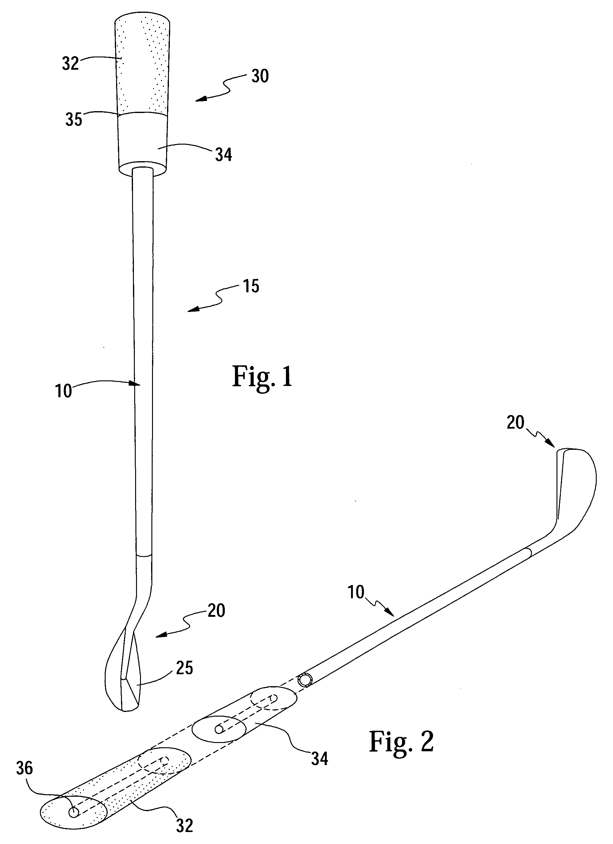
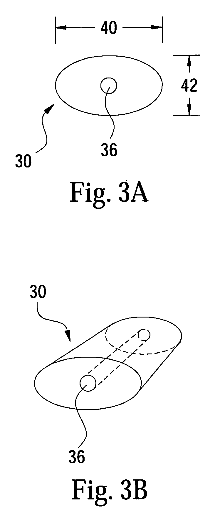
[0038]As shown in FIG. 1, a golf club 15 comprises shaft 10, head 20, and grip (or handle) 30. The head 20 is attached to the lower end of the shaft 10, which will be referred to as the head-end of the shaft. Similarly, the grip 30 is attached to the upper end of the shaft 10, which will be referred to as the handle-end of the shaft.

[0039]The shaft 10 may be a standard golf club shaft, and it may be made of steel, graphite, or other material(s). The shaft is of a standard length and weight. The head 20 may be any type of golf club head or blade that the golfer desires. Regardless of the particular structure or design of the club head, almost all club heads include an elongated, substantially flat surface 25, referred to as the face, with which the golf ball is to be struck. Many, many head designs are currently being manufactured and are well known to those skilled in the art. Any method of attachment of the shaft 10 to the head 20 is acceptable. Such methods include adhesive means,...


PUM


Abstract

A conventional length golf club with a grip including a heavy counterweight, the mass of which is sufficient to cause the center of gravity of the whole golf club to be located within the boundaries of the grip. The counterweight may be an elongated member with a bore through its interior, and in order to achieve the object of placing the center of gravity within the boundaries of the grip, it must have a substantially larger cross-section than the standard-diameter shaft of a golf club. The grip may include a lower support section made of a substantially less massive material than the counterweight. In a preferred embodiment, the grip has an elliptical cross section with the major axis of the ellipse perpendicular to the face of the club head.

Description

[0001]This application is a continuation-in-part of patent application Ser. No. 09 / 420,128 filed on Oct. 19, 1999 now U.S. Pat. No. 6,506,128 and claims priority thereto.BACKGROUND OF THE INVENTION[0002]Too often tradition drives design, and golf is an ancient sport. When golf was invented some 500 years ago, a simple stick was state-of-the-art. Featured today, and for all practical purposes unchanged for half a millennia, the maximum diameter of the handle end of a typical golf club shaft is about half an inch. This small diameter may be necessary with full-swing clubs, because of the different functions of the left and right hands—the lower hand finger grip must roll the club over near impact while the upper hand balances the club under the heel pad of the palm. However, because the hands perform similar functions in a putting stroke, this small diameter grip is unnecessary.[0003]In fact, the full swing and putting stroke are entirely different. In a full swing, the golfer's feet,...

Claims


Application Information

Patent Timeline
IPC IPC(8): A63B53/00A63B53/14A63B49/02A63B49/08A63B59/00A63BA63B1/00
CPCA63B53/007A63B53/145A63B49/08A63B53/00A63B59/0025A63B59/0029A63B59/0092A63B60/08A63B60/10A63B60/12A63B60/14A63B60/24A63B60/54A63B60/00
Inventor BLOOM, JR., JAMES PIERCE
Owner BLOOM JR JAMES PIERCE
Learn More