Piezoelectric shear resonator, composite piezoelectric shear resonator, and piezoelectric resonator component

a piezoelectric shear resonator and composite piezoelectric technology, applied in piezoelectric/electrostrictive/magnetostrictive devices, piezoelectric/electrostriction/magnetostriction machines, piezoelectric/electrostrictive/magnetostrictive devices, etc., can solve the problem of inability to provide a thickness-shear resonator with a large specific band, piezoelectric shear

Inactive Publication Date: 2005-11-22
MURATA MFG CO LTD
View PDF5 Cites 8 Cited by
  • Summary
  • Abstract
  • Description
  • Claims
  • Application Information

AI Technical Summary

Benefits of technology

[0016]With this arrangement, the holding member is used to support the composite piezoelectric shear resonator without affecting the vibration characteristics of the vibrating member. Thus, this arrangement provides an improved advantage in that miniaturization can be achieved while increasing the specific band, compared to an energy-trapping-type resonator.
[0017]According to a further preferred embodiment of the present invention, a composite piezoelectric shear resonator includes a vibrating member that has a piezoelectric element for exciting a shear-vibration mode and excitation electrodes that are respectively provided on opposing major surfaces of the piezoelectric element, the vibrating member being made of a material having a first acoustic impedance Z1. The composite piezoelectric shear resonator further includes first and second reflective layers that are coupled with corresponding ends of the vibrating member, each reflective layer including material having a second acoustic impedance Z2 that is lower than the first acoustic impedance Z1, and first and second holding members that are coupled with corresponding ends of the first and second reflective layers, respectively, the ends being opposite to the ends with which the vibrating member is coupled, each second holding member including material having a third acoustic impedance Z3 that is higher than the second acoustic impedance Z2. Thus, vibrations propagating to the first and second reflective layers from the vibrating member are reflected at the interface between the first reflective layer and the first holding member and at the interface between the second reflective layer and the second holding member, respectively. With this arrangement, vibrations propagating to the reflective layer from the vibrating member are reflected at the interface between the reflective layer and the holding member. Thus, the composite piezoelectric shear resonator can be mechanically supported without adversely affecting the vibration characteristics of the vibrating member, and thus the entire configuration thereof can be miniaturized.

Problems solved by technology

Such a configuration, however, makes it difficult to provide a thickness-shear resonator having a large specific band (i.e., the ratio of the passband width to the center frequency).
The piezoelectric shear resonator having the above-described configuration is not suitable for miniaturization since it involves a large amount of area for providing a vibration damping region, i.e., a region between a vibrating portion to a non-vibrating portion.
In practice, however, even such a piezoelectric shear resonator cannot provide an increased specific band.

Method used


Image

  • Piezoelectric shear resonator, composite piezoelectric shear resonator, and piezoelectric resonator component
  • Piezoelectric shear resonator, composite piezoelectric shear resonator, and piezoelectric resonator component
  • Piezoelectric shear resonator, composite piezoelectric shear resonator, and piezoelectric resonator component

Examples


first preferred embodiment

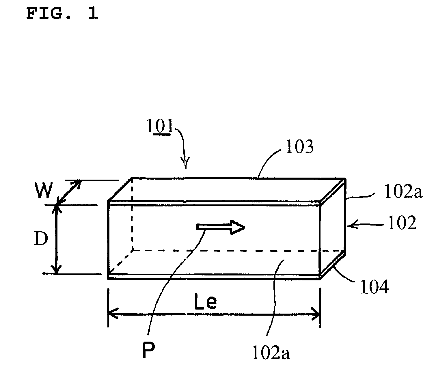
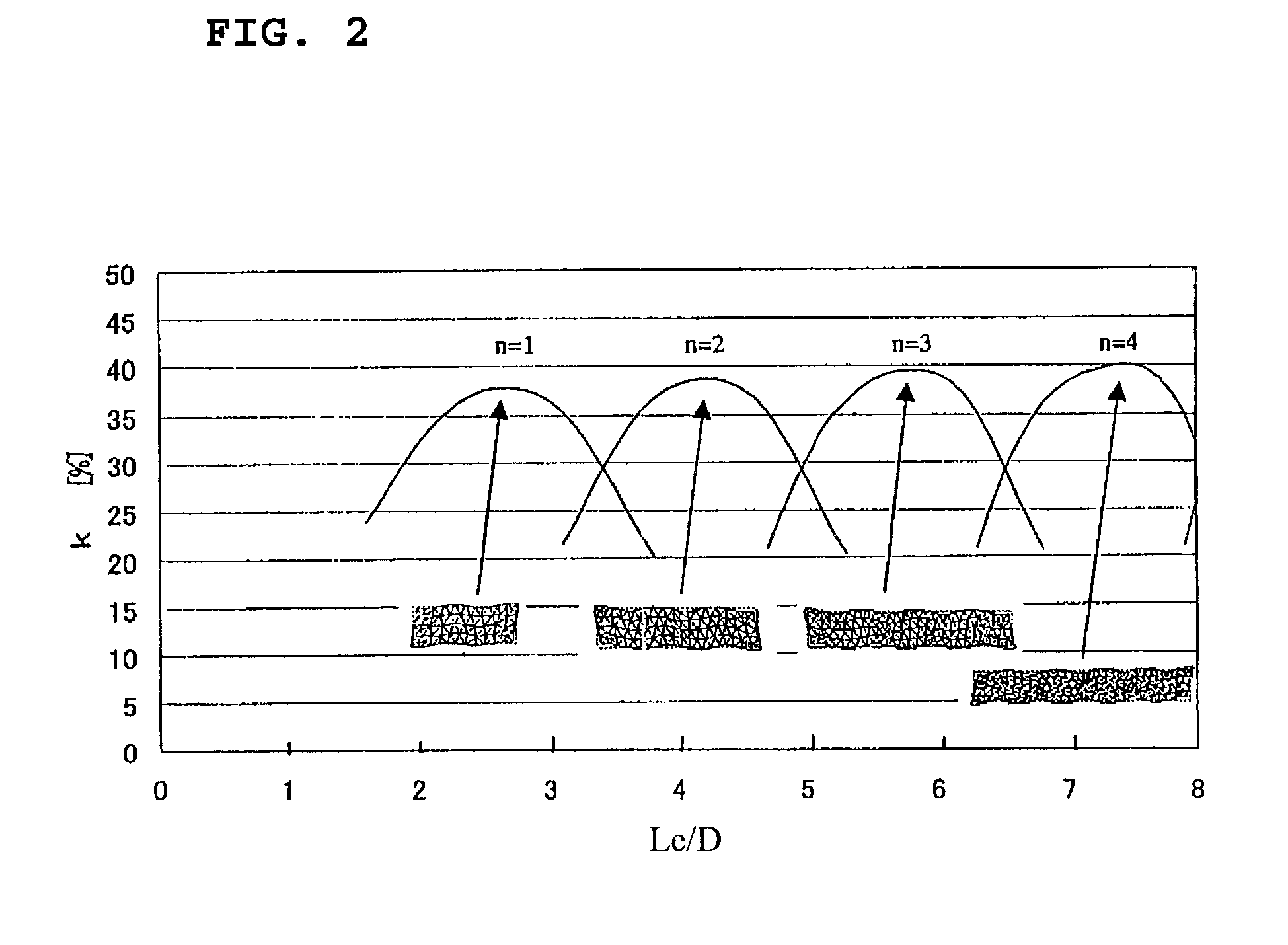
[0047]FIG. 1 is a perspective view schematically showing the configuration of a piezoelectric shear resonator according to a first preferred embodiment of the present invention. FIG. 2 is a graph showing the aspect ratio Le / D of shear strain surfaces versus an electromechanical coupling factor k. FIG. 3 is a graph showing the aspect ratio Le / D of the shear strain surfaces versus an elastic compliance S44E / S33E. FIG. 4 is a side view schematically showing the configuration of the piezoelectric shear resonator. FIG. 5 is a graph showing a ratio L / Le, L being the overlapping length of opposing excitation electrodes and Le being the horizontal dimension of the shear strain surfaces, versus a frequency shift dFOSC / FOSC. FIG. 6 is a graph showing a ratio W / D, W being the distance between the opposing shear strain surfaces, i.e., the width dimension of the piezoelectric element, and D being the horizontal dimension of the shear strain surfaces, versus the electromechanical coupling factor ...

second preferred embodiment

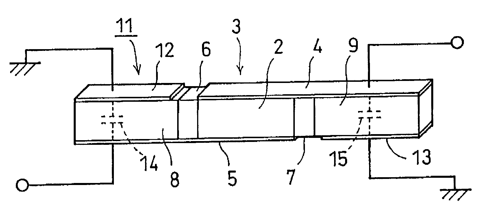
[0059]FIG. 7 is a perspective view schematically showing the configuration of a composite piezoelectric shear resonator according to a second preferred embodiment of the present invention, and FIG. 8 is a perspective view schematically showing the configuration according to a modification thereof. Reference number 111 in FIG. 7 indicates a composite piezoelectric shear resonator according to a second preferred embodiment, and reference numeral 112 in FIG. 8 indicates a composite piezoelectric shear resonator according to a modification of the second preferred embodiment.

[0060]The composite piezoelectric shear resonator 111 according to the second preferred embodiment preferably has a substantially rectangular-column vibrating member 113, reflective layers 114 and 115 that are respectively coupled with the opposing end-surfaces of the vibrating member 113 in the axial direction (longitudinal direction), and holding members 116 and 117 that are respectively coupled with the outer end-...

third preferred embodiment

[0067]FIG. 9 is a perspective view schematically showing the entire structure of a composite piezoelectric shear resonator according to a third preferred embodiment of the present invention, and FIG. 10 is a side view thereof. FIG. 11 is a graph showing a ratio |Lr1−Lr2| / (Lr1+Lr2), which is based on the difference between the lengths of the reflective layers of the composite piezoelectric shear resonator, versus the ratio of change (hereinafter referred to as a “change ratio”) dFr / Fr of the resonant frequency Fr. FIG. 12 is a graph showing the ratio |Lr1−Lr2| / (Lr1+Lr2) versus the specific-bandwidth change ratio (the ratio of change of the specific bandwidth) of a spurious vibration. FIG. 13 is a graph showing a ratio h / T, h being the length of the holding members of the piezoelectric shear strain resonator and T being the thickness thereof, versus the electromechanical coupling factor k.

[0068]FIG. 14 is a graph showing the ratio h / T versus the electromechanical coupling factor k whe...


PUM


Abstract

A piezoelectric shear resonator has a substantially rectangular-column piezoelectric element that excites a shear-vibration mode and that has opposing substantially rectangular shear strain surfaces. The shear strain surfaces each have an aspect ratio at which the electromechanical coupling factor reaches substantially a maximum value. When the vertical dimension of the shear strain surfaces is D and the horizontal dimension thereof is Le, the aspect ratio Le/D is expressed by Le/D={α·(S44E/S33E)1/2+β}±0.3, where S44E and S33E are elastic compliances, α=0.27·n+0.45, β=1.09·n+0.31, and n is a positive integer.

Description

BACKGROUND OF THE INVENTION[0001]1. Field of the Invention[0002]The present invention relates to piezoelectric shear resonators and composite piezoelectric shear resonators. More specifically, the present invention relates to a piezoelectric shear resonator for use, for example, as a vibrating member in a composite piezoelectric shear resonator and also relates to a composite piezoelectric shear resonator, except an energy-trap resonator, using the piezoelectric shear resonator as a vibrating member.[0003]The present invention further relates to composite piezoelectric shear resonators and piezoelectric resonator components. More particularly, the present invention relates to a composite piezoelectric shear resonator having a configuration in which vibrations propagating to a reflective layer from a vibrating member are reflected at an interface between the reflective layer and a holding member and also relates to a piezoelectric resonator component including the composite piezoelec...

Claims


Application Information

Patent Timeline
Patent Type & Authority Patents(United States)
IPC IPC(8): H03H9/00H03H9/17H03H9/125H03H9/13H02N2/00H03H9/02H03H9/05
CPCH03H9/02157H03H9/177
Inventor MITANI, AKIHIROKAIDA, HIROAKI
Owner MURATA MFG CO LTD
Why Eureka
Try Eureka