Pre-configured light modules

a technology of pre-configured light modules and light sources, applied in the field of pre-configured light sources, can solve the problems of reducing production yield and cost, reducing production efficiency, and high cost of standardized cameras, and avoiding the use of standardized cameras

Active Publication Date: 2005-11-22
AVAGO TECH INT SALES PTE LTD
View PDF11 Cites 46 Cited by
  • Summary
  • Abstract
  • Description
  • Claims
  • Application Information

AI Technical Summary

Problems solved by technology

Unfortunately, the LED fabrication process provides LEDs having emissions and efficiencies that vary somewhat from one LED to another.
Such variations are often unacceptable.
Unfortunately, this solution reduces the production yield and cost increases.
These standardized cameras are usually expensive because their responses are tuned to correspond to the standard spectral responses.
These sensors typically do not conform to a standard color scheme.
One problem with using such sensors is that a calibration procedure is required to map the spectral responses of the sensor to the LED light source spectral output.
This increases the capital investment needed to establish the production line.

Method used


Image

  • Pre-configured light modules
  • Pre-configured light modules
  • Pre-configured light modules

Examples


Embodiment Construction

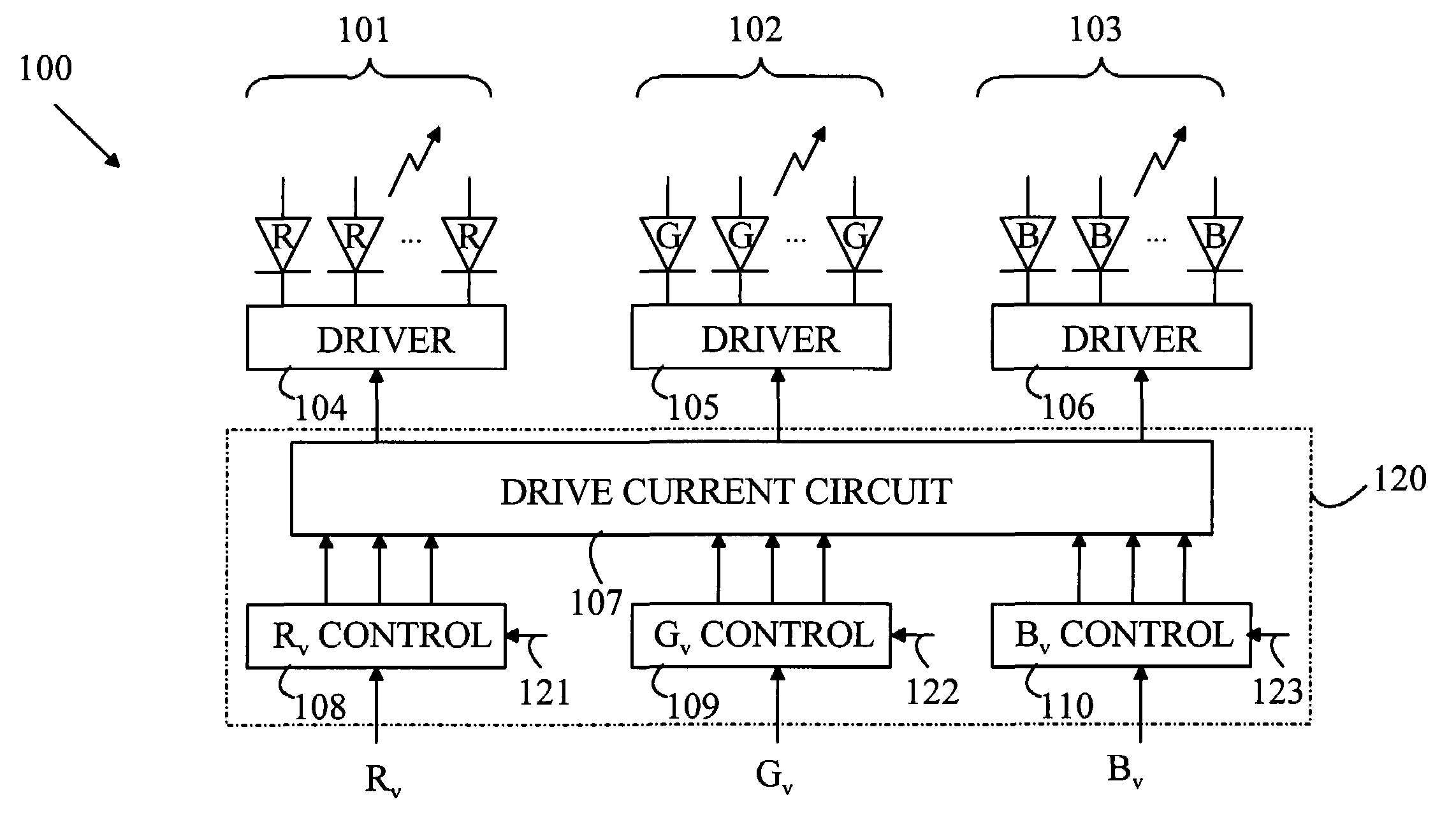
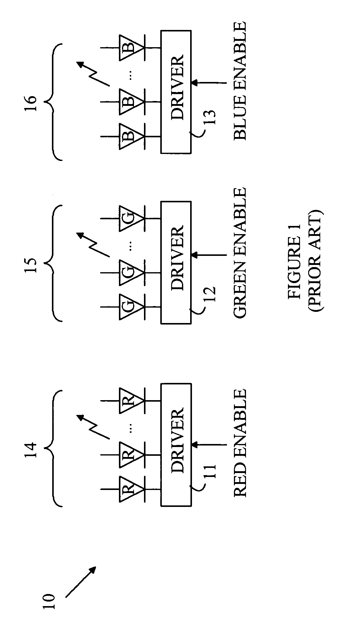
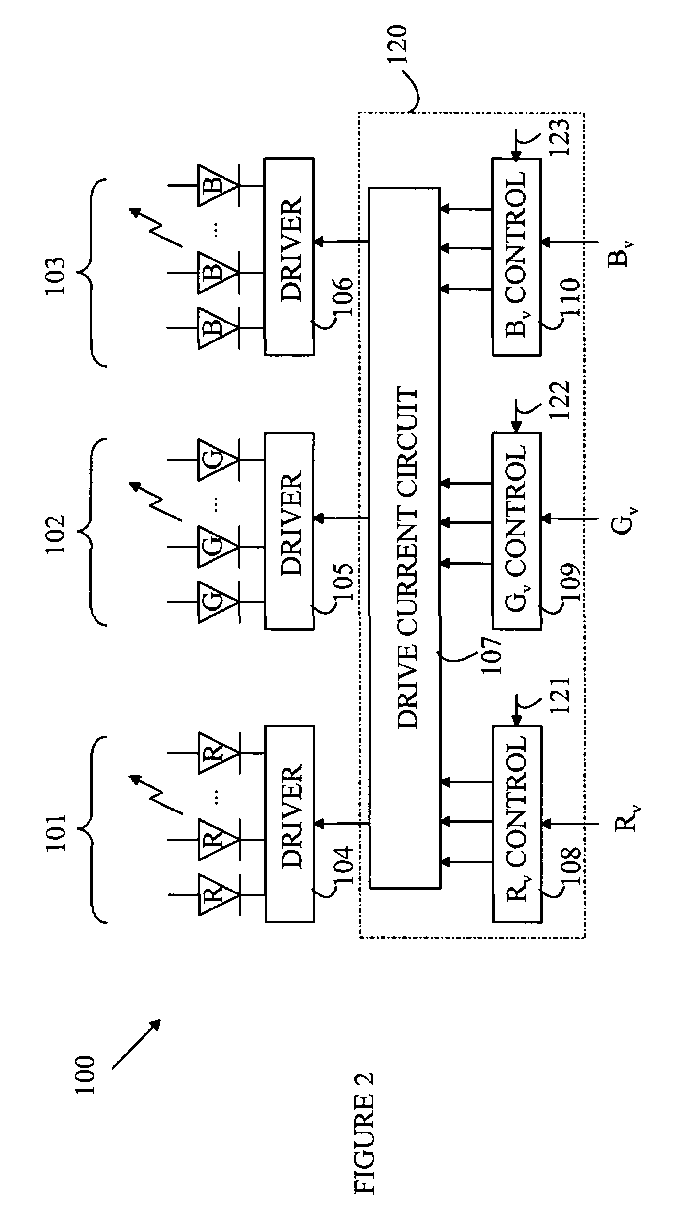
[0009]The present invention provides a method for constructing a pre-configured compound light source for use in a lighting system that employs spectral feedback to control the emitted light, such that calibration of the sensor can be performed without the need for expensive test equipment. The manner in which the present invention provides its advantages can be more easily understood with reference to FIG. 1, which illustrates a prior art compound light source 10. Light source 10 is constructed from three arrays of LEDs shown at 14–16. Arrays 14–16 emit light in the red, green, and blue spectral ranges, respectively. Arrays of LEDs of each color are used instead of a single LED to increase the light output of the light source. The intensity of light generated by each array is determined by the current flowing through the LEDs in that array or by the duty cycle of a pulsing signal that is applied to each LED. For the purposes of this discussion, it will be assumed that the intensity...


PUM


Abstract

The present invention includes a light source having N light generators, a receiver, and an interface circuit. Each light generator emitting light of a different wavelength, the intensity of light generated by the kth generator is determined by a signal Ik coupled to that light generator. The receiver receives a color coordinate that includes N color components, Ck, for k=1 to N, wherein N is greater than 1. The interface circuit generates the Ik for k=1 to N from the received color components and a plurality of calibration parameters. The calibration parameters depend on manufacturing variations in the light generators. The calibration parameters have values chosen such that a light signal generated by combining the light emitted from each of the light generators is less dependent on the manufacturing variations in the light generators than a light signal generated when Ik is proportional to Ck for k=1 to N.

Description

FIELD OF THE INVENTION[0001]The present invention relates to light sources.BACKGROUND OF THE INVENTION[0002]Light emitting diodes(LEDs) are attractive candidates for replacing conventional light sources such as incandescent lamps and fluorescent light sources. The LEDs have higher light conversion efficiencies and longer lifetimes. Unfortunately, an LED produces light in a relatively narrow spectral band. Hence, to produce a light source having an arbitrary color, a compound light source having multiple LEDs is typically utilized or part of the light from a single LED must be converted to light of a second wavelength, which is mixed with the light from the original LED. For example, an LED-based white light source that provides an emission that is perceived as white by a human observer can be constructed by combining light from arrays of red, blue, and green emitting LEDs that are generating the correct intensity of light at each color. Similarly, light of other spectral emissions c...

Claims


Application Information

Patent Timeline
Patent Type & Authority Patents(United States)
IPC IPC(8): H05B44/00H05B37/02
CPCY10S362/80H05B45/22H05B45/20H05B45/00
Inventor LIM, KEVIN LEN LILEE, JOON CHOKJAFFAR, RIZAL BIN
Owner AVAGO TECH INT SALES PTE LTD
Why Eureka
Try Eureka