Image processing apparatus and method, and storage medium

a technology of image processing and storage media, which is applied in the direction of image enhancement, digital output to print units, instruments, etc., can solve the problems of low print throughput, low data transfer rate and data size that the printer can hold, and poor efficiency, so as to achieve low redundancy and improve image quality.

Inactive Publication Date: 2005-11-22
CANON KK
View PDF9 Cites 21 Cited by
  • Summary
  • Abstract
  • Description
  • Claims
  • Application Information

AI Technical Summary

Benefits of technology

[0007]The present invention has been made to solve the aforementioned problems, and has as its object to generate quantization data with low redundancy by quantizing image data without deteriorating image quality.

Problems solved by technology

The size of image data to be transferred increases and the time required for transferring image data from the host computer to the printer increases with increasing resolution of printer, resulting in a low print throughput.
However, as the printer requires higher resolution and higher speed, the data transfer rate and the data size that the printer can hold pose a problem.
That is, when highly redundant information that expresses five tones using 4 bits is transferred to the printer, this results in very poor efficiency.
However, a reduction of the number of tones leads to loss of tone information, production of false contours, an increase in granularity, and the like, thus deteriorating the image quality of an output image.

Method used


Image

  • Image processing apparatus and method, and storage medium
  • Image processing apparatus and method, and storage medium
  • Image processing apparatus and method, and storage medium

Examples


first embodiment

(Arrangement)

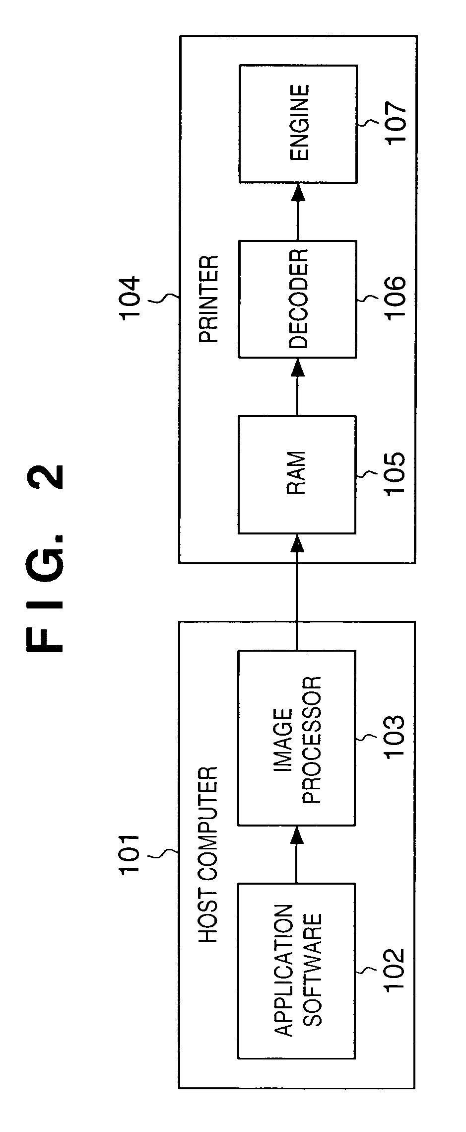
[0025]FIG. 2 is a block diagram showing the arrangement of an image processing system according to this embodiment.

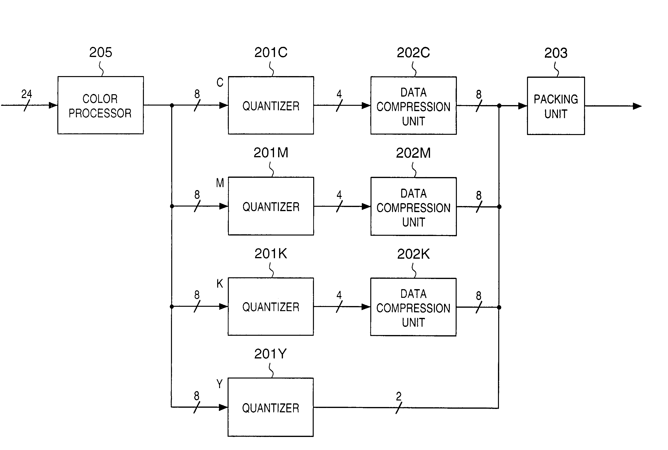
[0026]Application software 102, which runs on a host computer 101 and is used to create and edit an image, outputs image data of the created and / or edited image to an image processor 103. Image data output from the application software 102 is 8-bit multi-valued data per color of R, G, and B or C, M, Y, and K if an image is a continuous tone image.

[0027]The image processor like a printer driver which runs on the host computer 101 executes a quantization process, compression process, and the like of the input image data, thus generating image data to be transferred to a printer 104 such as an ink-jet printer.

[0028]The image data input to the printer 104 is stored in a RAM 105. Since the image data stored in the RAM 105 has been compressed by the image processor 103, it is expanded to image data to be printed by a decoder 106. The expanded image data is sent t...

second embodiment

[0041]An image processing apparatus according to the second embodiment of the present invention will be described below. Note that the same reference numerals in this embodiment denote the same parts as in the first embodiment, and a detailed description thereof will be omitted.

[0042]In the second embodiment, the compression process of the data compression unit 202 described in the first embodiment is ON / OFF-controlled depending on image data. FIG. 9 is a block diagram showing the arrangement of the image processor 103 of the second embodiment. In FIG. 9, a data compression controller 204 is added to the arrangement of the first embodiment shown in FIG. 3. The data compression controller 204 computes the memory size that the printer 104 requires for processing on the basis of, e.g., the size of image data input to the image processor 103. When the memory size that the printer 104 can use is smaller than the required memory size, the data compression controller 204 controls image dat...

third embodiment

[0046]An image processing apparatus according to the third embodiment of the present invention will be explained below. Note that the same reference numerals in this embodiment denote the same parts as in the first embodiment, and a detailed description thereof will be omitted.

[0047]The data compression process in the first embodiment is done on the host computer 101 side. By contrast, the data compression process in the third embodiment is done on the printer 104 side. FIG. 11 is a block diagram showing the arrangement of an image processing system according to the third embodiment.

[0048]In the third embodiment, since the host computer 101 does not perform any compression, the quantized image data is directly transferred from the image processor 103 to the printer 104. Hence, in the example explained in the first embodiment, 4-bit image data that has been quantized to 5-valued data is directly transferred to the printer 104. The image data input to the printer 104 is compressed by ...


PUM

PropertyMeasurementUnit
memory sizeaaaaaaaaaa
coloraaaaaaaaaa
sizeaaaaaaaaaa

Abstract

When highly redundant information that expresses five tones using 4 bits is transferred to a printer in terms of a unit data length in data transfer, efficiency is very poor. Hence, multi-valued data is quantized to 5-valued data, which is output as a 4-bit code that can express five values. 4-bit codes for three bits are combined to be converted into an 8-bit code. The 8-bit codes are packed into data of a 16-bit unit, and the packed data is transferred to the printer.

Description

FIELD OF THE INVENTION[0001]The present invention relates to an image processing apparatus and method, and a storage medium and, more particularly, to an image processing apparatus and method for quantizing image data.BACKGROUND OF THE INVENTION[0002]When a printer such as an ink-jet printer, the number of tones that can output is limited, is used, the number of tones of image data is reduced to that the printer can express by a quantization process by means of a printer driver on a host computer, and that image data is then transferred from the host computer to the printer.[0003]The size of image data to be transferred increases and the time required for transferring image data from the host computer to the printer increases with increasing resolution of printer, resulting in a low print throughput. In such case, the following method may be used. That is, the printer driver sends only tone information of a density pattern using a density pattern method, and the printer converts the...

Claims


Application Information

Patent Timeline
Patent Type & Authority Patents(United States)
IPC IPC(8): H04N1/64H04N1/41G06F3/12B41J2/52G06T5/00H04N1/46
CPCH04N1/648
Inventor KONNO, YUJIISHIKAWA, HISASHITAJIKA, HIROSHIFUJITA, MIYUKIKAWATOKO, NORIHIROEDAMURA, TETSUYAMAEDA, TETSUHIRO
Owner CANON KK
Why Eureka
Try Eureka