System and method for remote analysis and control of test and measurement devices

a technology remote analysis, applied in the field of system and method for remote analysis and control can solve the problems of system errors, difficult use of test and measurement device by most users, and failure to use analysis probes

Inactive Publication Date: 2005-11-22
JDS UNIPHASE CORP
View PDF5 Cites 13 Cited by
  • Summary
  • Abstract
  • Description
  • Claims
  • Application Information

AI Technical Summary

Benefits of technology

[0010]Briefly described, in architecture the remote analysis and control system can be implemented as follows. A remote analysis and control tool kit is shipped to the test and measurement device user. The remote analysis and control tool kit includes a processing device with a modem that is connected to a video camera. The video camera provides video images through the processing device and the modem so that the remote analysis and control tool kit may transmit video across a network to a systems engineer located at a vendor call center. The remote analysis and control tool kit also includes control software that enables a systems engineer to provide control instructions to the test and measurement device and the system under test, and request status data from both the test and measurement device and the system under test.
[0011]The present invention can also be viewed as a method for remote analysis of test and measurement equipment. In this regard, the method can be broadly summarized by the following steps: connecting the remote analysis and control tool kit to the test and ...

Problems solved by technology

As is known in the electrical arts, when a new electrical device is developed or being utilized, the system can exhibit errors.
The use of test and measurement devices has never been easy for most users.
One of the most difficult tasks when using a test and measurement device has been connecting the test and measurement device to the device under test correctly.
However, the use of an analysis probe is not always successful and the developers and users of an electronic device will still have problems connecting test and measurement devices to the device under te...

Method used


Image

  • System and method for remote analysis and control of test and measurement devices
  • System and method for remote analysis and control of test and measurement devices
  • System and method for remote analysis and control of test and measurement devices

Examples


Embodiment Construction

[0021]The invention will now be described with reference to the drawings, wherein like reference numerals designate corresponding parts throughout the several views. Although the invention will be described in connection with these drawings, there is no intent to limit it to the embodiment or embodiments disclosed therein. On the contrary, the intent is to include all alternatives, modifications, and equivalents included within the spirit and scope of the invention as defined by the appended claims.

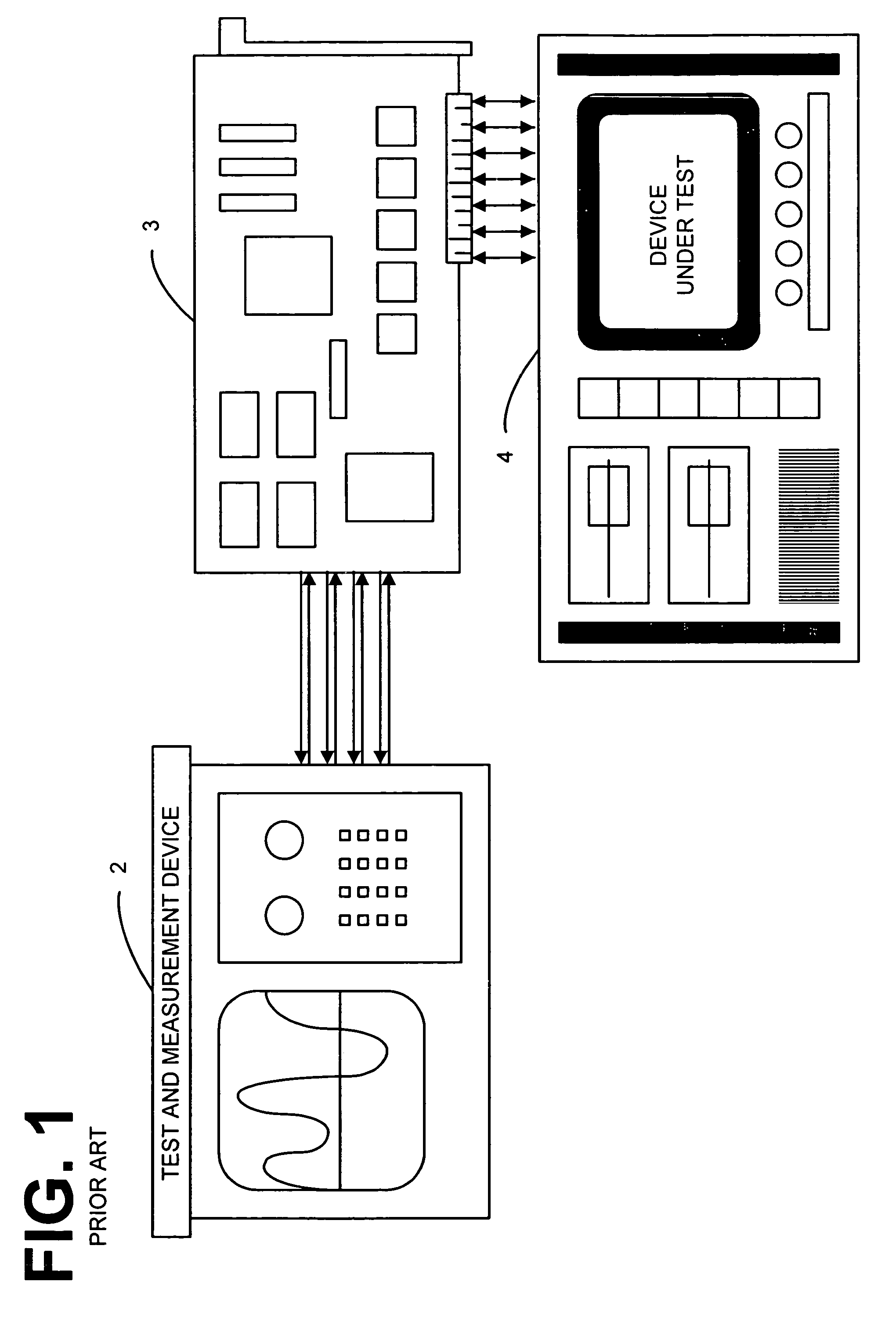
[0022]Illustrated in FIG. 1 is the logic analysis system of the prior art. A conventional test and measurement device 2 and a conventional device under test 4 each generally comprise a processor (not shown) and a memory (not shown) which can be either one or a combination of the common types of memory, for example, but not limited to, erasable programmable read only memory (EPROM), electronically erasable programmable read only memory (EEPROM), flash memory, programmable read only memory ...


PUM


Abstract

A system and method for remote analysis and control of test and measurement devices for diagnosis and troubleshooting problems for users of the test and measurement devices. The remote analysis and control tool kit includes a processing device with a modem that is connected to a video camera. The video camera provides video images through the processing device back through the modem so that the remote analysis and control tool kit may transmit video across a network to a call center systems engineer. The remote analysis and control tool kit also includes control software that enables a systems engineer to provide control instructions to the test and measurement device and the system under test, and request status data from both the test and measurement device and the system under test.

Description

BACKGROUND OF THE INVENTION[0001]1. Field of the Invention[0002]The present invention generally relates to a system and method for providing remote control of test and measurement devices and devices under test. Specifically, the system and method of the present invention provide for a system and method engineered to access a customer test and measurement device and devices under test for determining proper hookup and to perform remote testing.[0003]2. Description of Related Art[0004]As is known in the electrical arts, when a new electrical device is developed or being utilized, the system can exhibit errors. As a consequence, developers and users of these new electrical devices can utilize many techniques to check for proper functioning of the electronic device and diagnose these errors. One of the test and measurement devices that developers use to debug electronics is a logic analyzer. The use of test and measurement devices has never been easy for most users. One of the most dif...

Claims


Application Information

Patent Timeline
IPC IPC(8): G01R31/02G06F17/50G01R35/00G06F11/25G06F11/273
CPCG01R35/00G06F11/2294G06F11/25
Inventor AHRENS, MARK LEEASHBY, STEVEN ROBERTGASPARI, DAVID MARKOSBORN, LARRY JAMESGONZALEZ, ORLANDO JOSEPH
Owner JDS UNIPHASE CORP
Why Eureka
Try Eureka