On-press developable lithographic printing plate precursor

Inactive Publication Date: 2005-11-29
FUJIFILM HLDG CORP +1
View PDF13 Cites 33 Cited by
  • Summary
  • Abstract
  • Description
  • Claims
  • Application Information

AI Technical Summary

Benefits of technology

[0011]An object of the present invention is to provide an on-press developable heat-sensitive lithographic printing plat

Problems solved by technology

However, since the plate precursor as exposed has no visible image but a latent one, it is

Method used


Image

  • On-press developable lithographic printing plate precursor
  • On-press developable lithographic printing plate precursor
  • On-press developable lithographic printing plate precursor

Examples


Example

Example 1

[0129]A coating composition for image forming layer having the formulation shown below was applied to the aluminum support with a bar coater to a dry coating weight of 1.0 g / m2 and dried in an oven at 80° C. for 90 seconds to prepare a lithographic printing plate precursor.

Coating Composition for Image Forming Layer:

[0130]
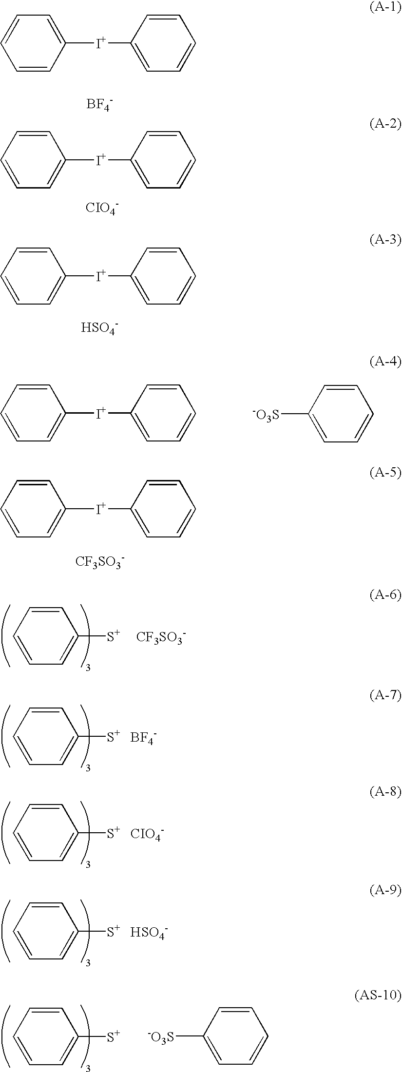
Water100gMicrocapsules (1) (on a solid basis)5gAcid generator A-50.5gFluorine type surface active agent (Megafac F-171 fromDainippon Ink & Chemicals, Inc.)0.05g

[0131]The resulting printing plate precursor was imaged on a Creo Trendsetter 3244VX equipped with a water-cooled 40 W infrared semiconductor laser under conditions of an output power of 17 W, an external drum rotation speed of 150 rpm, an energy density of 200 mJ / cm2 at the image plane, and a resolution of 2400 dpi. The exposed area turned purple blue to form a printed-out image with a contrast enough to be distinguished from the unexposed area. The density difference between the exposed and unexpo...

Example

Example 2

[0133]A lithographic printing plate precursor was produced in the same manner as in Example 1, except for using the microcapsules (2) in place of the microcapsules (1). On imagewise exposure, the exposed area turned purple blue to form a printed-out image with a contrast enough to be distinguished from the unexposed area. The density difference between the exposed and unexposed areas was 0.35 measured with Gretag Macbeth D19C. On printing in the same manner as in Example 1, the plate precursor was developed on press and became capable of printing. Close observation of the 10th copy with a 20× magnifier revealed excellent density uniformity on the solid image area and no stains on the non-image area. Printing was continued to get more than 20,000 impressions without causing fine lines and text missing, density unevenness in a solid image area and scumming.

Example

Example 3

[0134]A lithographic printing plate precursor was produced in the same manner as in Example 1, except for using the microcapsules (3) in place of the microcapsules (1). On imagewise exposure, the exposed turned black to form a printed-out image with a contrast enough to be distinguished from the unexposed area. The density difference between the exposed and unexposed areas was 0.36 measured with Gretag Macbeth D19C. On printing in the same manner as in Example 1, the plate precursor was developed on press and became capable of printing. Close observation of the 10th copy with a 20× magnifier revealed excellent density uniformity on the solid image area and no stains on the non-image area. Printing was continued to get more than 20,000 impressions without causing fine lines and text missing, density unevenness in a solid image area, and scumming.


PUM


Abstract

An on-press developable heat-sensitive lithographic printing plate precursor comprising: a support having a water-wettable surface; and an image forming layer, wherein the image forming layer comprises microcapsules containing a lipophilic compound and one of a leuco dye which forms a color by an action of an acid and a dye which reduces the maximum absorption intensity in a visible region by an action of an acid, an acid generator capable of generating an acid on heat application, and a light-heat converting substance.

Description

FIELD OF THE INVENTION[0001]This invention relates to an on-press developable heat-sensitive lithographic printing plate precursor comprising a water-wettable support and an image forming layer containing microcapsules. More particularly, it relates to a heat-sensitive lithographic printing plate precursor which is fit for imaging by infrared scanning exposure based on digital signals and for on-press development and capable of forming a printed-out image on imagewise exposure.BACKGROUND OF THE INVENTION[0002]Computer-to-plate (CTP) technology has recently seen marked development, and a number of studies have been given to printing plate precursors for CTP. In pursuit of further streamlining the platemaking process and addressing the waste water problem, plate precursors that can be mounted on a printing press after imagewise exposure without requiring chemical development have been researched, and various techniques have been proposed to date.[0003]A so-called on-press development ...

Claims


Application Information

Patent Timeline
IPC IPC(8): B41C1/10
CPCB41C1/1008B41C1/1016B41C2201/02B41C2201/14B41C2210/04B41C2210/08B41C2210/22B41C2210/24
Inventor INNO, TOSHIFUMI
Owner FUJIFILM HLDG CORP
Why Eureka
Try Eureka