PWM controlled motor drive

a technology of pulse width modulation and motor drive, which is applied in the direction of electric controllers, electronic commutators, dynamo-electric converter control, etc., can solve the problems of failure to reduce current to zero, difficulty in increasing, and difficulty in decreasing current,

Inactive Publication Date: 2005-11-29
PANASONIC CORP
View PDF11 Cites 10 Cited by
  • Summary
  • Abstract
  • Description
  • Claims
  • Application Information

AI Technical Summary

Benefits of technology

[0016]An object of the present invention is providing a PWM controlled motor driver capable of operating a motor stably without occurrence of breakdown of a switching element or degradation of the efficiency of the motor even when the phase of a current supplied to the motor tends to delay such as during high-speed rotation of the motor.
[0018]According to the invention described above, PWM control for suppressing sharp abnormal increase of a phase current can be provided. In particular, when the number of times of switching operation performed for a switching element decreases during a time period corresponding to a predetermined electrical angle due to delay of the phase of a current supplied to the motor with respect to a position signal indicating the position of a rotor of the motor, a switching element for a phase for which the magnitude of the current should be decreased is turned OFF in the time period corresponding to the next predetermined electrical angle. This prevents a switching element from receiving a current of a magnitude exceeding its absolute maximum rating.

Problems solved by technology

As described above, in the motor driver of FIG. 9, in the case that the load of the motor is large, for example, the current of a phase for which the current should be increased finds difficulty in increasing, while the current of a phase for which the current should be decreased finds difficulty in decreasing, due to influence of an induced voltage and the like.
As a result, the phase of the phase current supplied to the motor delays with respect to a position signal PS indicating the position of the rotor, causing a problem that the current of a phase for which the current should be decreased fails to decrease to zero within the time period corresponding to the electrical angle 60°.
This disadvantageously generates brake torque on the motor and thus degrades the efficiency of the motor.

Method used


Image

  • PWM controlled motor drive
  • PWM controlled motor drive
  • PWM controlled motor drive

Examples


Embodiment Construction

[0035]Hereinafter, a preferred embodiment of the present invention will be described with reference to the accompanying drawings. In the embodiment to follow, the case that a motor driver drives a 3-phase brushless motor will be described as an example.

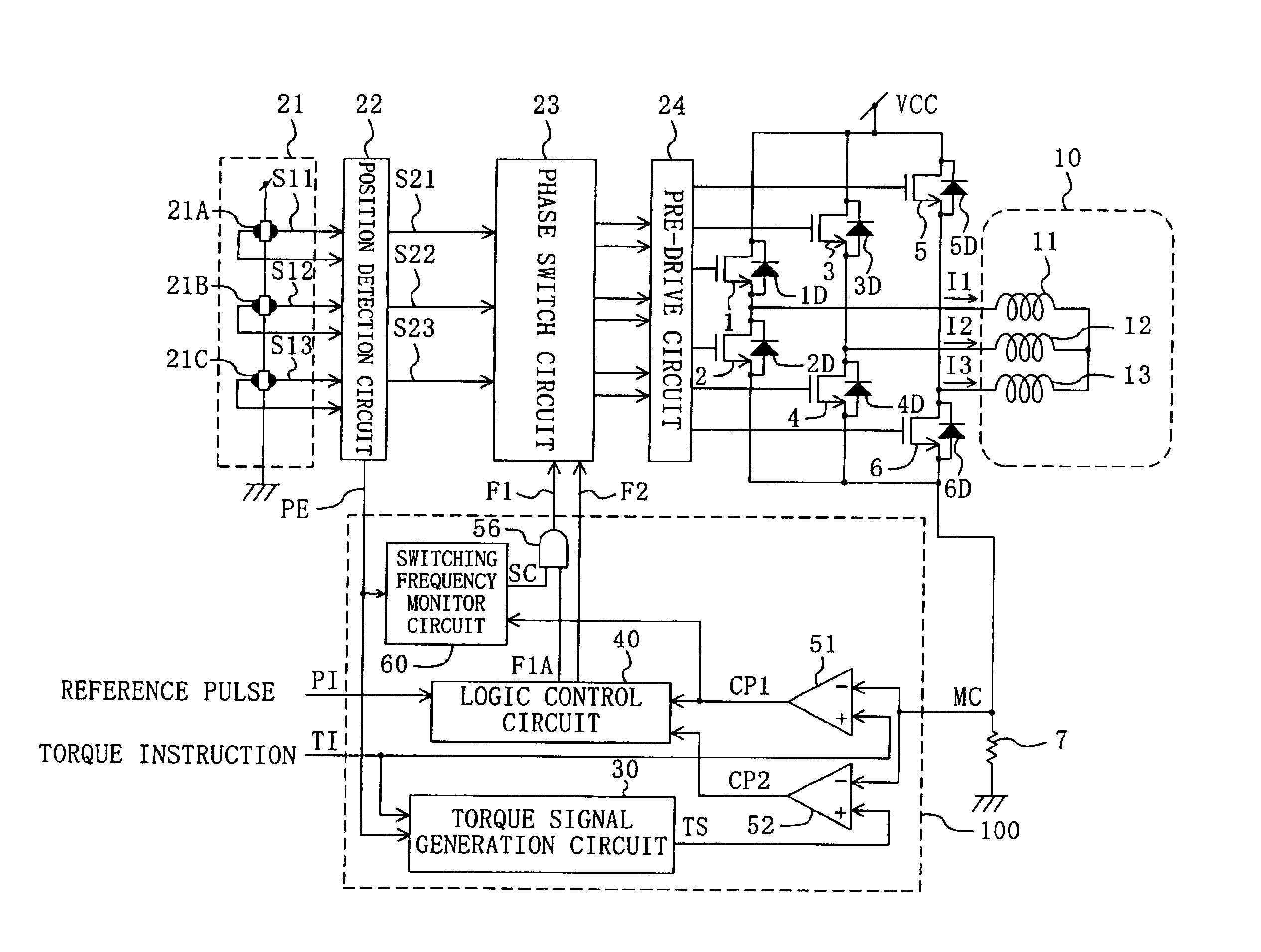
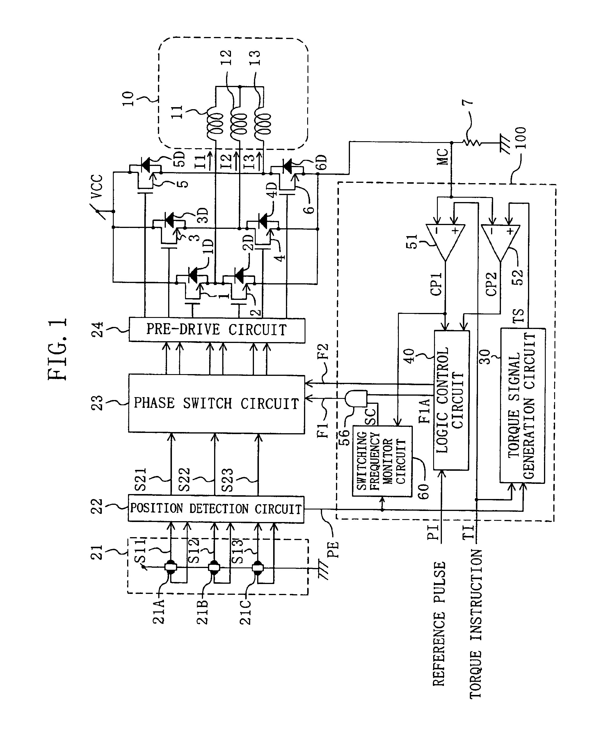
[0036]FIG. 1 is a block diagram of a motor driver of an embodiment of the present invention and a motor driven with the motor driver. The motor driver of FIG. 1 includes U-phase, V-phase and W-phase upper arm side drive transistors 1, 3 and 5, U-phase, V-phase and W-phase lower arm side drive transistors 2, 4 and 6, diodes 1D, 2D, 3D, 4D, 5D and 6D, a current detection resistance 7, a Hall sensor circuit 21, a position detection circuit 22, a phase switch circuit 23, a pre-drive circuit 24 and an conduction period control section 100.

[0037]The conduction period control section 100 includes a torque signal generation circuit 30, a logic control circuit 40, comparators 51 and 52, an AND gate 56 and a switching frequency monitor circuit ...


PUM


Abstract

The motor driver having a plurality of output circuits each having two switching elements connected in series includes: a phase switch circuit for putting a switching element on one side of one output circuit among the plurality of output circuits in the ON state during a time period corresponding to a predetermined electrical angle, and performing switching operation for switching elements on the other side of plural output circuits among the remaining output circuits; and a conduction period control section. The conduction period control section generates a signal for controlling the switching operation. Specifically, when the number of times of switching operation performed during the time period corresponding to the predetermined electrical angle is equal to or less than a predetermined value, a switching element corresponding to a phase, for which the magnitude of the current should be decreased, is turned OFF in the time period corresponding to the next predetermined electrical angle.

Description

BACKGROUND OF THE INVENTION[0001]The present invention relates to motor drive technology, and more particularly, to a motor drive technology of a pulse width modulation (PWM) system.[0002]FIG. 9 is a block diagram of a conventional motor driver and a motor driven with the motor driver. FIG. 2 is a graph showing target waveforms of phase currents for a motor 10. A position detection circuit 22 outputs signals corresponding to the position of a rotor of the motor 10 based on outputs of a Hall sensor circuit 21. A torque signal generation circuit 30 generates a signal TS of a sawtooth wave having a peak value corresponding to a torque instruction voltage TI and a period equal to the time period corresponding to an electrical angle of 60° of the motor 10. A logic control circuit 40 generates switching operation control signals F1 and F2 for defining the time period during which drive transistors 1 to 6 are put in the ON state. A phase switch circuit 23 turns ON the drive transistors 1 t...

Claims


Application Information

Patent Timeline
Patent Type & Authority Patents(United States)
IPC IPC(8): H02P6/12H02P6/06H02P6/08
CPCH02P6/142H02P6/16H02P6/15Y02P80/10
Inventor SAKAI, HIROFUMIYOKOUCHI, TOMOHARUMARUYAMA, KEN
Owner PANASONIC CORP
Why Eureka
Try Eureka