Redundant clock module

a clock module and redundant technology, applied in the field of electronic oscillators, can solve the problems of unwanted frequency, common failure mode of oscillators that are not presently adequately addressed, and control oscillators that fail frequently, etc., and achieve the effect of high reliability

Active Publication Date: 2005-11-29
NEL FREQUENCY CONTROLS
View PDF46 Cites 27 Cited by
  • Summary
  • Abstract
  • Description
  • Claims
  • Application Information

AI Technical Summary

Benefits of technology

[0007]The redundant clock module of the present invention preferably comprises at least two crystal oscillators, detection circuitry, switching circuitry and control circuitry. The redundant clock module of the present invention targets mission critical applications where clock redundancy is required. The redundant clock module supplies a highly reliable fixed clock reference output based on one of the at least two internal reference oscillators that are monitored to make sure that they are operating properly and within tolerance. If the primary oscillator fails or is out of tolerance, the redundant clock module will detect the failure or out of tolerance condition and switch to a secondary working oscillator to take over primary timing functions. The redundant clock module provides a slow seamless transition between switching to assure no significant phase shift or runt pulses will affect the end user application.

Problems solved by technology

These oscillators have common failure modes that are not presently adequately addressed in the prior art.
Crystal controlled oscillators commonly fail to start at the correct frequency, but will generate a signal that is often within the operational range of the circuitry that it is driving.
In these instances, the electronic circuitry may continue to operate, but at an unwanted frequency.
Failures of a crystal controlled oscillator are not limited to a clock source that is stuck high or low, but an oscillator that is out of frequency tolerance due to the oscillator operating on the wrong crystal overtone order or mode, an oscillator operating in a spurious mode of the crystal, or an oscillator not operating on the crystal at all.
Disadvantages of the above ICs is that they don't detect free running clocks (oscillators that are not crystal controlled, but still within the operating frequency range of the IC) and they don't detect out of tolerance conditions.
Another disadvantage of the above ICs is that they have higher jitter and phase noise than most high stability applications can tolerate, compared to the hybrid solution of the present invention.

Method used


Image

  • Redundant clock module
  • Redundant clock module
  • Redundant clock module

Examples


Embodiment Construction

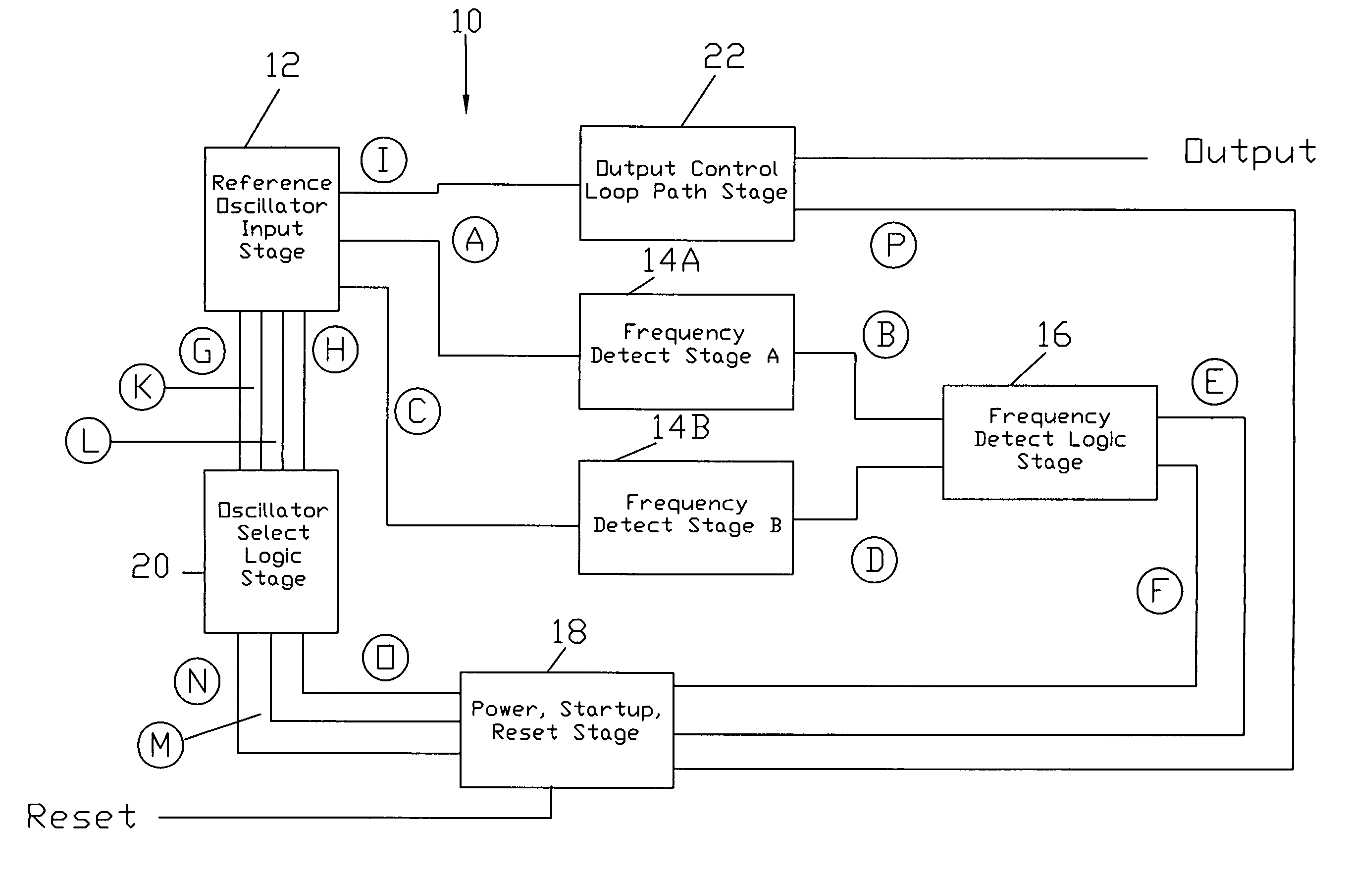
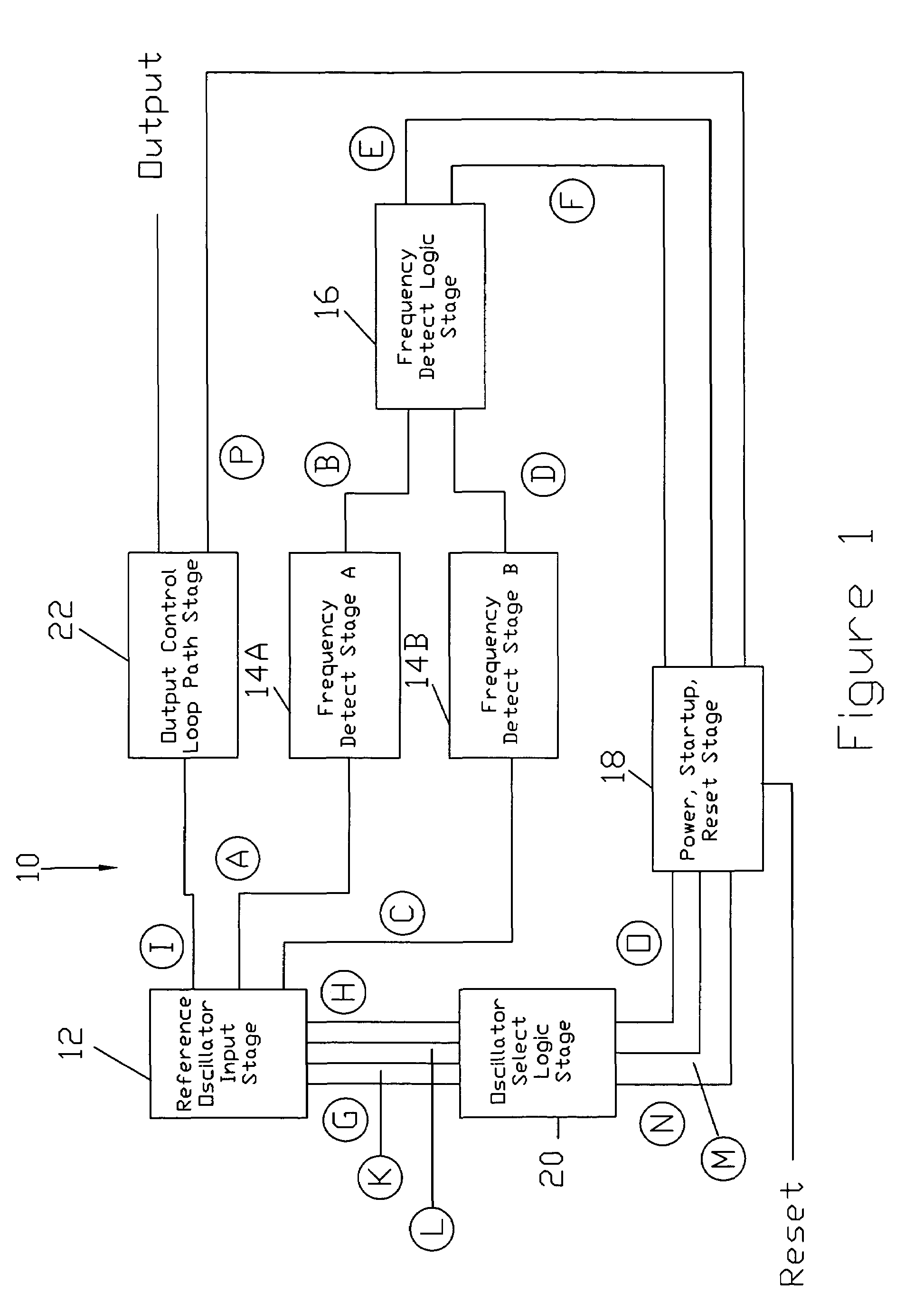
[0022]The redundant clock module of the present invention is preferably comprised of at least two crystal oscillators, detection circuitry, switching circuitry and control circuitry. The redundant clock module of the present invention is designed to continuously supply a highly reliable fixed clock reference at its output. The clock reference output is based on one of at least two internal clock references that are continuously monitored and eliminated from use if they fail or are not operating within tolerance. A slow transition between oscillator references during switching is controlled to assure no significant phase shift or runt pulses will affect the end user application. The frequency range of the redundant clock module of the present invention is preferably from 20.000 MHz to 250.000 MHz, with a user specified frequency tolerance from ±100 ppm, jitter of 5 psec rms max, and ECL compatible outputs.

[0023]Referring now to the drawings, FIG. 1 is a block diagram of the redundant...


PUM


Abstract

A redundant clock module provides a highly reliable fixed clock reference output. This clock reference output is based on at least two internal reference oscillators that are monitored and eliminated from use if they are not operating or within tolerance requirements. The redundant clock module comprises at least two oscillators, detection circuitry, switching circuitry and control circuitry. If a primary oscillator fails or is out of tolerance, the redundant clock module will detect the failure or out of tolerance condition and switch to a secondary working and in tolerance oscillator to take over primary timing functions of an end user application. The redundant clock module provides a slow and seamless transition between oscillator switching to assure no significant phase shift or runt pulses will affect the end user application.

Description

CROSS-REFERENCE TO RELATED APPLICATIONS[0001]This application claims the benefits of U.S. Provisional Application No. 60 / 482,557, filed Jun. 25, 2003, the disclosure of which is incorporated herein by reference.BACKGROUND OF THE INVENTION[0002]The present invention relates generally to electronic oscillators, and more particularly to a redundant clock module for use in electronic circuits requiring a stable fail-safe oscillator. The present invention provides a primary clock source with at least one other alternate clock source that takes over for the primary clock source in the event of a failure or out of tolerance condition with the primary clock source. If the primary clock source fails or is out of tolerance, the circuitry of the present invention will detect the failure or out of tolerance condition and seamlessly switch to an alternate clock source.[0003]Crystal controlled oscillators are key system components that synchronize and distribute data signals for a wide variety of...

Claims


Application Information

Patent Timeline
Patent Type & Authority Patents(United States)
IPC IPC(8): H03L7/00H03L7/08
CPCH03L7/08
Inventor LICHTER, JERRY A.JONES, DAVID T.
Owner NEL FREQUENCY CONTROLS
Why Eureka
Try Eureka