Apparatus using in-band type access system

a technology of access system and transmission apparatus, applied in the field of transmission apparatus, can solve the problem of restricted conventional atm transmission system mentioned abov

Inactive Publication Date: 2005-11-29
FUJITSU LTD
View PDF13 Cites 13 Cited by
  • Summary
  • Abstract
  • Description
  • Claims
  • Application Information

AI Technical Summary

Benefits of technology

[0014]It is a general object of the present invention to provide an apparatus in which the above drawback is eliminated.

Problems solved by technology

However, the conventional ATM transmission system mentioned above is restricted to only a system having an operation / function in which cells are added and dropped as data on the transmission path / channel logically set on the payload carrier.

Method used


Image

  • Apparatus using in-band type access system
  • Apparatus using in-band type access system
  • Apparatus using in-band type access system

Examples


case 1

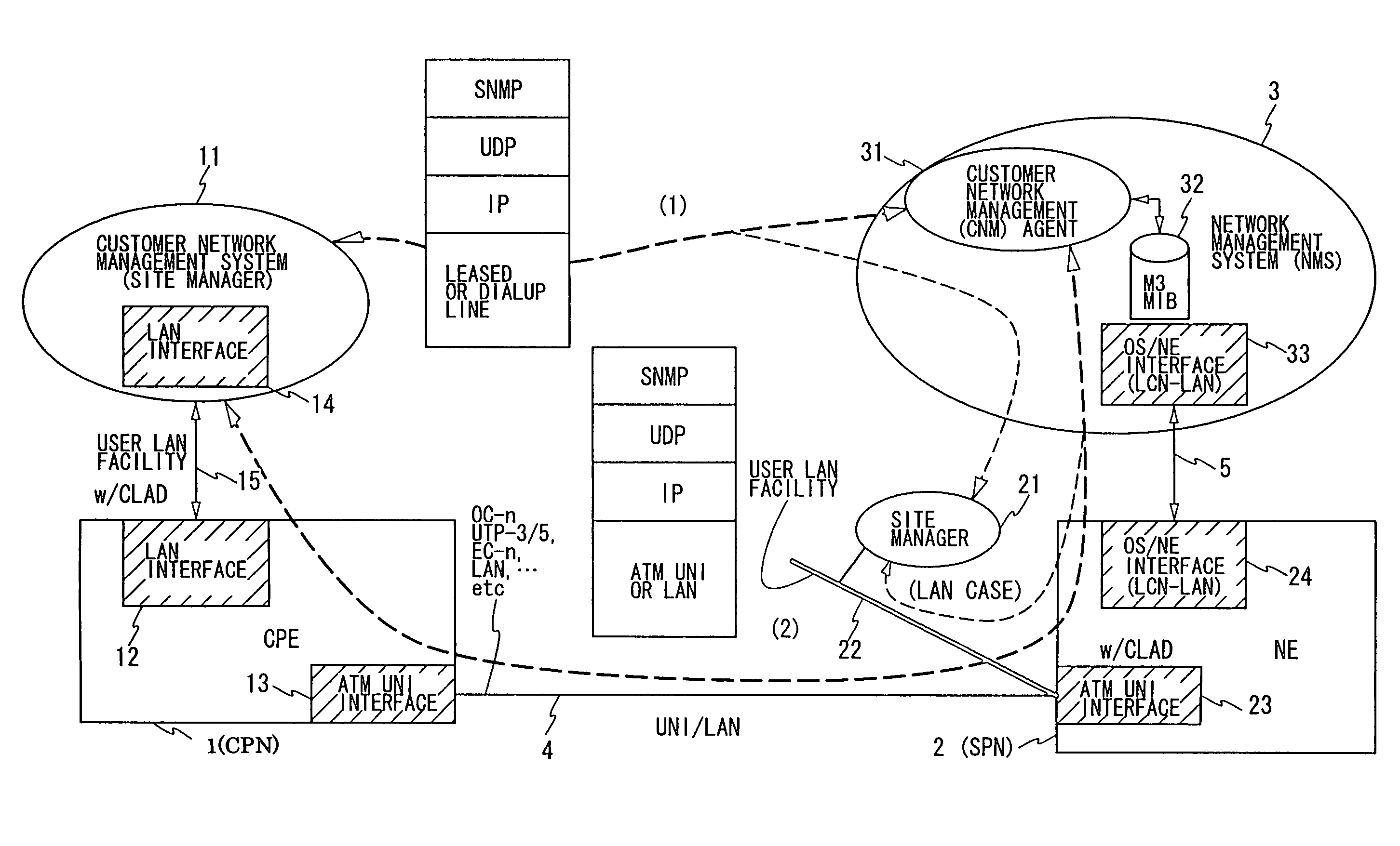
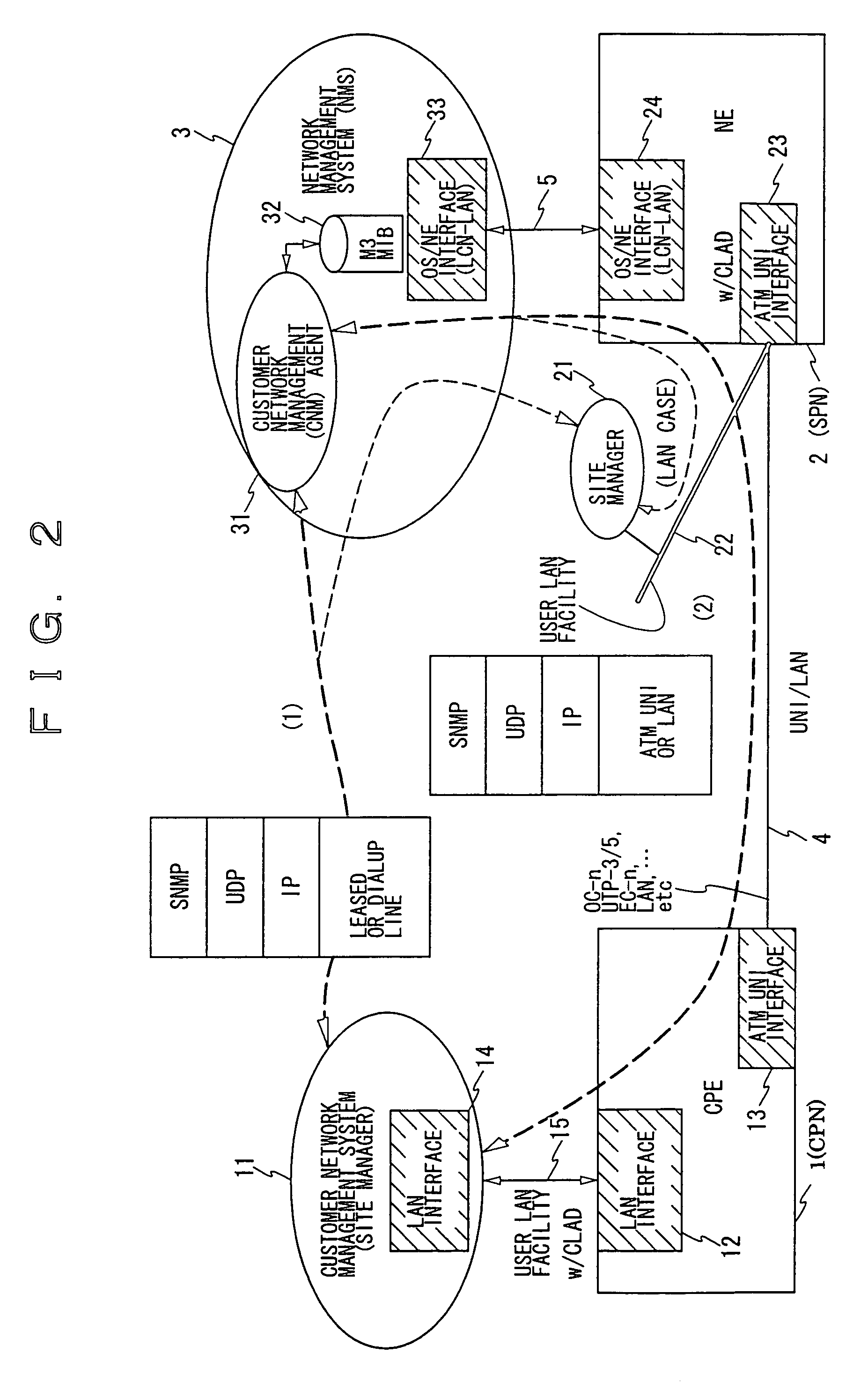
[0084](1) [0085]Case 1 is applied to a service interface called ATM / user network interface (ATM / UNI). The IP routing function of the customer premises equipment (CPE) inquires of the customer network management agent process 31 which VPI / VCI (Virtual Path Identifier / Virtual Channel Identifier) should be used to establish the SNMP management information path, that is, which particular cell transmission channel logically set on the payload carrier should be used. Then, the customer premises equipment (CPE) registers the VPI / VCI determined by the agent process 31 in its own local routing information table. Once the routing information is taken in the customer premises equipment, the ATM switch matrix part 63 of the present transmission apparatus can exchange, at any time, the SNMP management message in the same manner as that of an exchange of a message with a connection path, and can send the SNMP management message to the customer network management agent process 31 of the destinatio...

case 2

(2) [0086]Case 2 is applied to the LAN interface (LAN interface 61) which accommodates the CLAD unit. In this case, when the first SNMP management message arrives along with the IP address addressed to the customer network management agent process 31, the IP routing function of the LAN interface 61 operates and asks the IP packet switch part of a service process control part of the LAN interface 61 having predetermined PVC information to issue PVC information. Then, the IP routing function registers the PVC information thus obtained in its own LAN / IP routing information table located in a local position of the IP routing function. Thus, it becomes possible to easily add the values of the VPI / VCI obtained by the IP routing function of the LAN interface 61 to any incoming SNMP management message with the same IP address added thereto. As a result, it is possible to cause the SNMP message to pass through the PVC indicated by the PVC information and route it to the customer network mana...


PUM


Abstract

A transmission apparatus includes a part which sets a resource management information path based on a given network management protocol onto PVC logically set traffic defined in ATM switching so that a customer network management agent process and a user network management system can communicate with each other.

Description

BACKGROUND OF THE INVENTION[0001]1. Field of the Invention[0002]The present invention relates to a transmission apparatus using an in-band type SNMP (Simple Network Management Protocol) system.[0003]2. Description of the Related Art[0004]In a general transmission system, a group of apparatuses linked via transmission spans is located in a network forming the transmission system in a distributed formation. In such a real network configured by points (a group of apparatuses) and lines (a group of transmission lines), it is required to provide a management means or method for integrally managing the group of apparatuses and the group of transmission lines in such a manner that the network formed thereof is handled as only one object for management. Such a management means makes it possible to link the apparatuses arranged in the distributed formation and thus bring up the network to only one object.[0005]In an STM (SONET / SDH) transmission system, the management means or method is reali...

Claims


Application Information

Patent Timeline
Patent Type & Authority Patents(United States)
IPC IPC(8): H04L12/24H04L12/70G06F13/00H04Q11/04
CPCH04L41/0213H04L41/046H04L41/18H04L41/32H04Q11/0478H04L2012/5626H04L41/40
Inventor KOBAYASHI, SEIICHI
Owner FUJITSU LTD
Why Eureka
Try Eureka