Burner for a gas turbine engine

a gas turbine engine and burner technology, applied in the ignition of turbine/propulsion engines, engine starters, lighting and heating apparatus, etc., can solve the problems of limiting the mass of air available for pre-mixing, inability to achieve combustion stability, and partial blocking of parts of porosities, etc., to achieve the effect of reducing pressur

Inactive Publication Date: 2005-12-06
SOLAR TURBINES
View PDF7 Cites 79 Cited by
  • Summary
  • Abstract
  • Description
  • Claims
  • Application Information

AI Technical Summary

Problems solved by technology

However, increasing the mass of air may also lead to instabilities in combustion.
This requirement limits the mass of air available for pre-mixing.
These materials have a tendency to accumulate various particles eventually leading to partial blocking of portions of the porosities.

Method used


Image

  • Burner for a gas turbine engine
  • Burner for a gas turbine engine
  • Burner for a gas turbine engine

Examples


Embodiment Construction

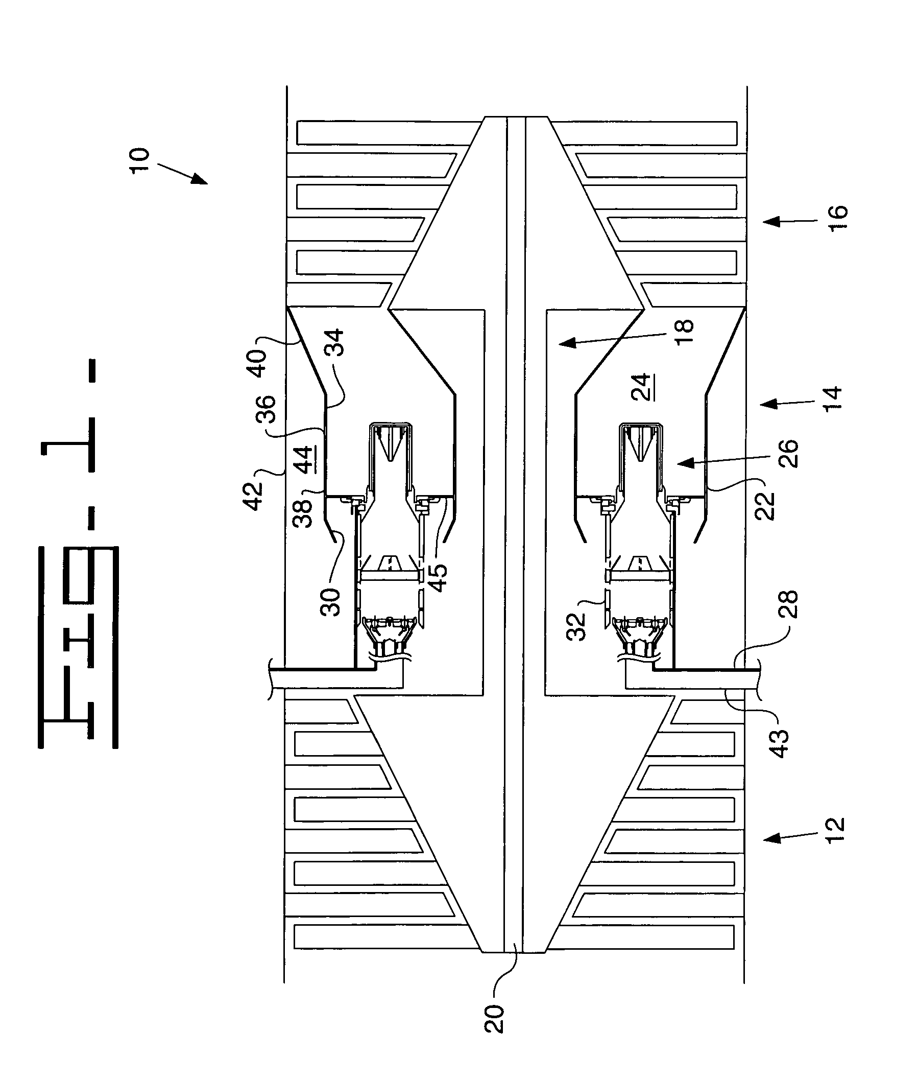
[0014]FIG. 1 shows a gas turbine engine 10 including a compressor section 12, a combustion system 14, and a turbine section 16. The compressor section 12 fluidly connects with the combustion system 14 to supply a compressed mass of air (not shown) to the combustion system 14. The turbine section 16 fluidly connects with the combustion system 14 and receives a mass of exhaust gas (not shown) from the combustion system 14. The mass of exhaust gas expands through the turbine section 16. The compressor section 12 and turbine section 16 connect through a force transmitting means 18 between the turbine section 16 and compressor section 12. In the present embodiment, the force transmitting means 18 is shown as a shaft 20. Other conventional methods for transmitting a force may include a hydraulic accumulator / motor, electric motor / generator, and gear systems.

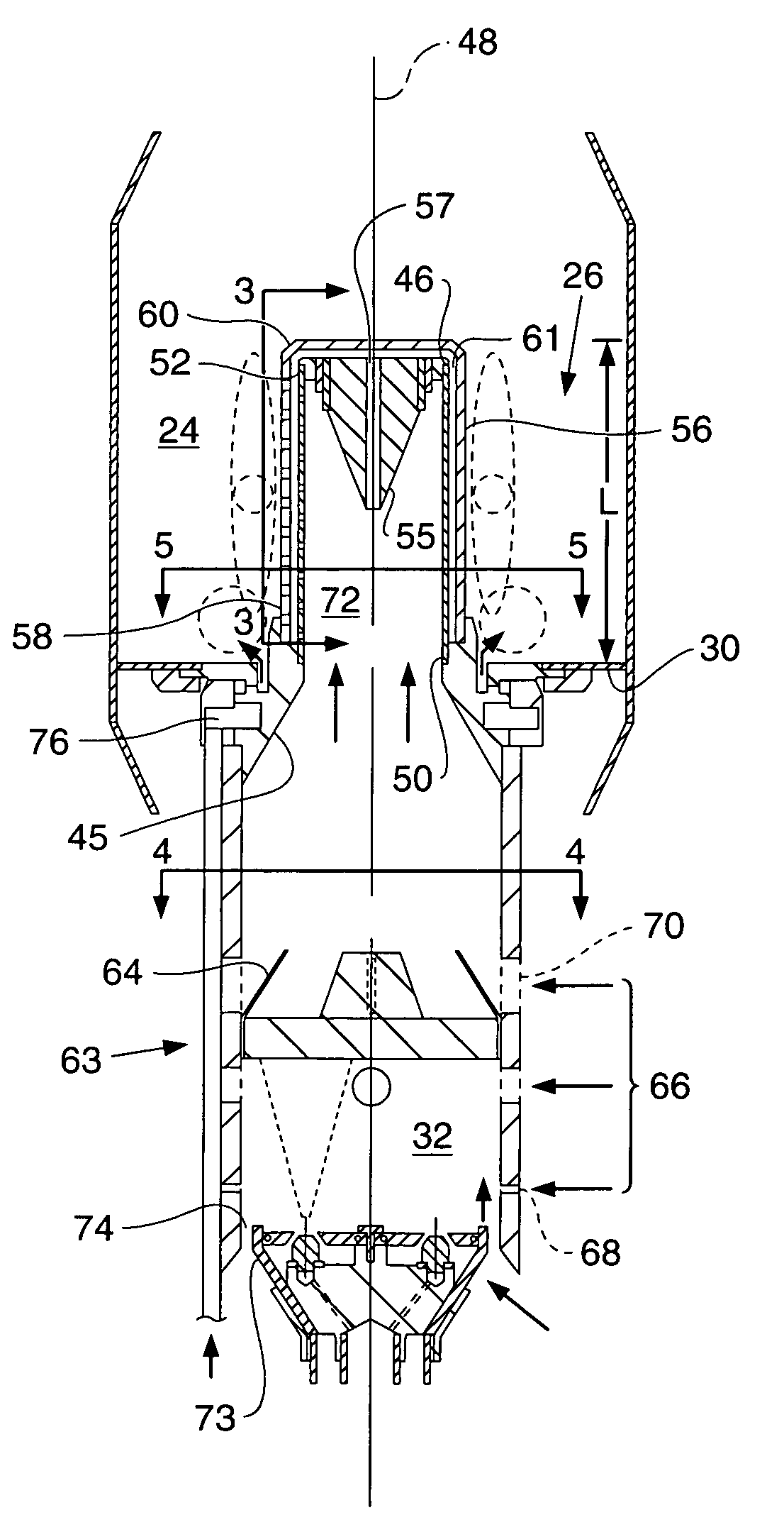
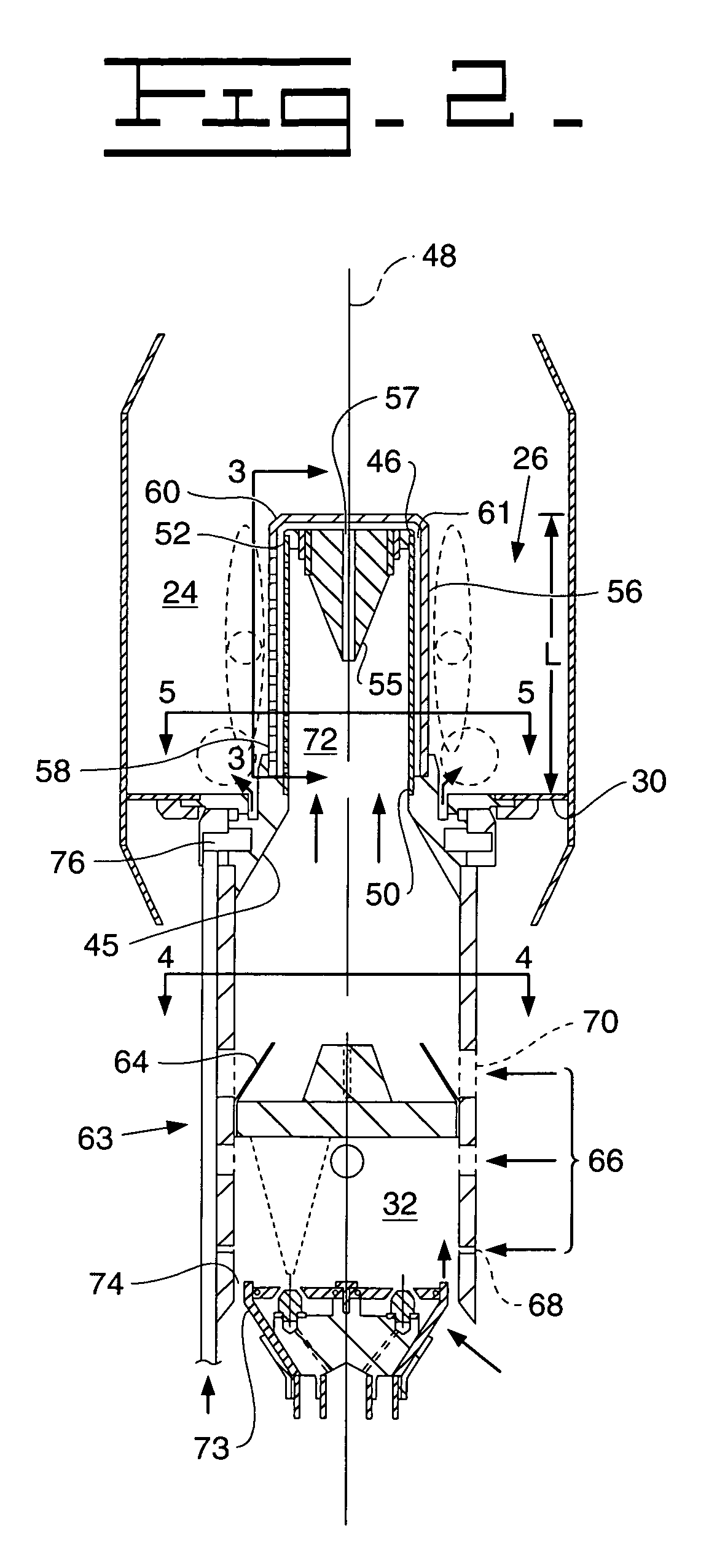
[0015]The combustion system 14 as shown in FIG. 1 may include a combustor liner 22, a fuel burner 26, a fuel supply line 28, a dome 30...


PUM


Abstract

To meet emissions standards, many gas turbine engines use some form of lean, pre-mixed combustion systems. These systems may lead to combustion oscillations or other instabilities. Jet combustion techniques provide a stable alternative lean, pre-mixed combustion system. The present invention presents a jet combustion system that includes a first cylinder having a first array of orifices. A second cylinder is positioned coaxially with the first cylinder. The second cylinder has a second array of orifices offset from the first array of orifices.

Description

TECHNICAL FIELD[0001]The present invention is directed to an apparatus and method for burning a mixture of fuel and air. More particularly, the present invention is directed to an apparatus and method for burning a mixture of fuel and air in a gas turbine engine.BACKGROUND[0002]Producers of gas turbine engines have made great strides in reducing regulated emissions such as NOx through a number of methods including lean, pre-mixed combustion systems (discussed in U.S. Pat. No. 5,660,045 issued to Ito et al. on 26 Aug. 1997) wherein a mass of fuel and a mass of air mix prior to ignition. The mass of air in such a system substantially exceeds the stoichiometric mass of air needed to chemically react with the mass of fuel. Further increasing the mass of air flowing through such a system may increase the NOx reduction by further reducing a primary combustion zone temperature. NOx emissions generally form when an excess of oxygen reacts with nitrogen at elevated temperatures. However, inc...

Claims


Application Information

Patent Timeline
Patent Type & Authority Patents(United States)
IPC IPC(8): F23R3/16F23R3/42
CPCF23R3/283F23R3/286F23R3/36F23D2900/11001F23R2900/00014F23R2900/03044
Inventor BOARDMAN, GREGORY A.
Owner SOLAR TURBINES
Why Eureka
Try Eureka