Numerically controlled lathe and method of machining work using this numerically controlled lathe
- Summary
- Abstract
- Description
- Claims
- Application Information
AI Technical Summary
Benefits of technology
Problems solved by technology
Method used
Image
Examples
second embodiment
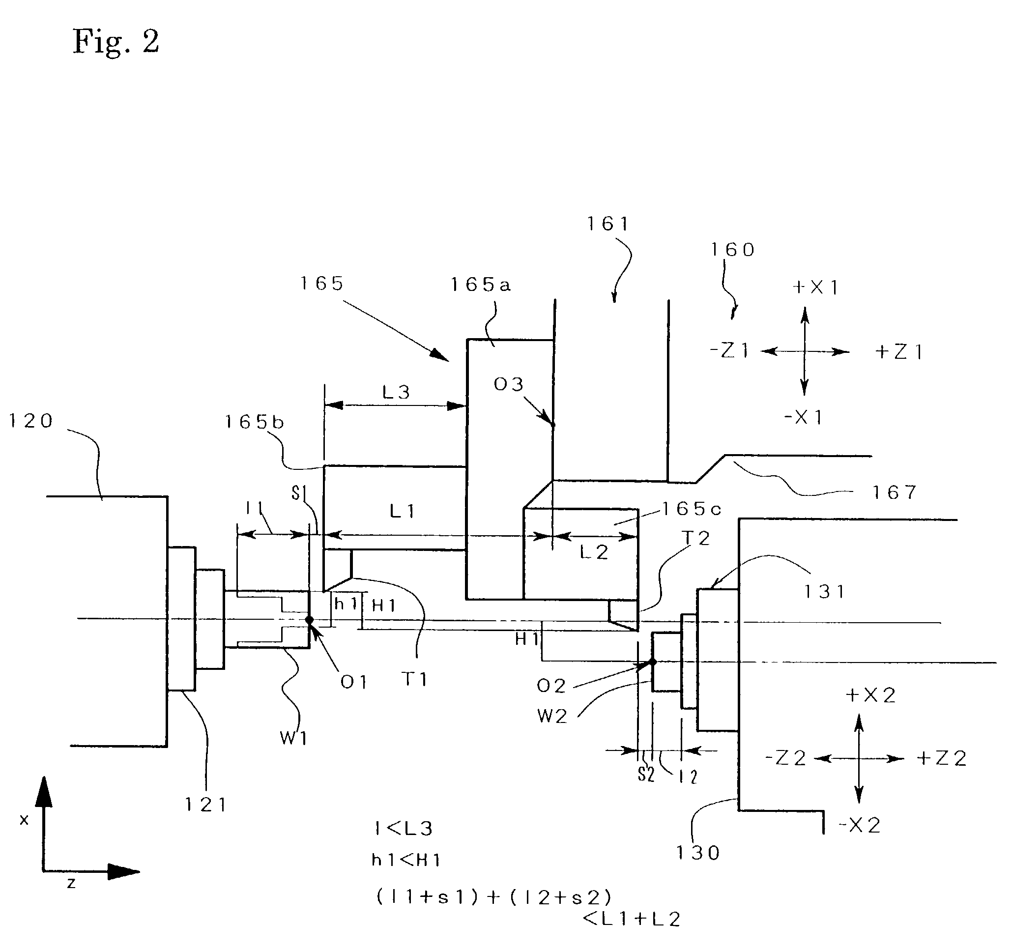
[0090]In the case of the second embodiment to be described below, the superposition of the Z0-axis and the Z1-axis is added besides the superposition of the X1-axis and the X2-axis, and the Z1-axis and the Z2-axis.
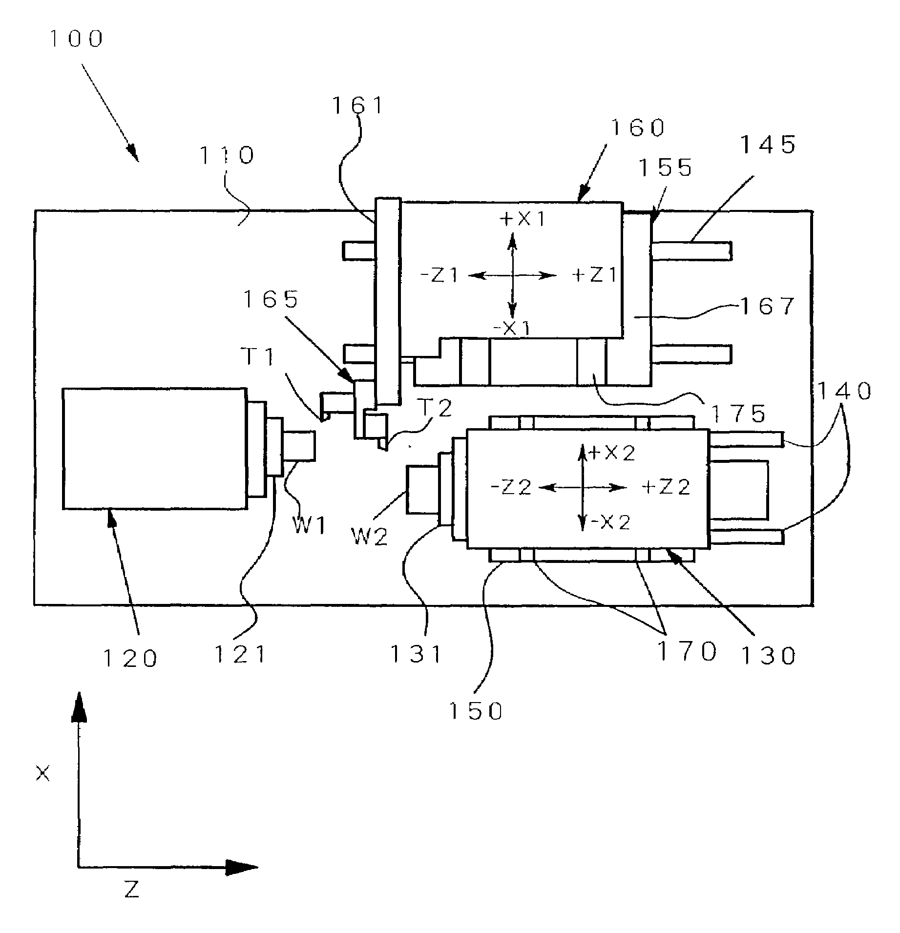
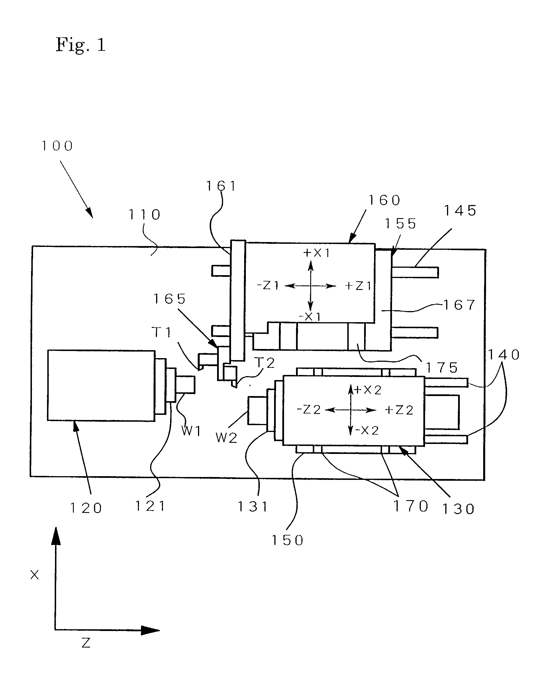
[0091]In FIG. 7, a plan view explaining the rough structure of the NC lathe according to the second embodiment of the present invention is shown, and in FIG. 8, a control block diagram of the control unit in this NC lathe is shown.
[0092]Furthermore, In FIG. 7 and FIG. 8, the same marks as those in FIG. 1 and FIG. 3 are given to the same parts and the same members as those in the first embodiment, and the detailed description of the parts and members will be omitted.
[0093]The first headstock 120′ of the NC lathe 100′ of the second embodiment is freely movable in the direction of the Z0-axis in parallel with the Z-axis. The movement in the direction of the Z0-axis of the first headstock 120′ is performed by the driving of a motor (not shown in the figure) which is the drivin...
PUM
| Property | Measurement | Unit |
|---|---|---|
| Time | aaaaa | aaaaa |
Abstract
Description
Claims
Application Information
 - R&D
- Intellectual Property
- Life Sciences
- Materials
- Tech Scout
- Unparalleled Data Quality
- Higher Quality Content
- 60% Fewer Hallucinations
Browse by: Latest US Patents, China's latest patents, Technical Efficacy Thesaurus, Application Domain, Technology Topic, Popular Technical Reports.
© 2025 PatSnap. All rights reserved.Legal|Privacy policy|Modern Slavery Act Transparency Statement|Sitemap|About US| Contact US: help@patsnap.com


