
Method for running a tufting machine

a tufting machine and tufting technology, applied in the field of tufting machines, can solve the problems of loose and uneven backstitches, product with lower quality, and the means of adjustment of current needlebar strokes are generally crud

Inactive Publication Date: 2005-12-06
GROZ BECKERT KG
View PDF10 Cites 21 Cited by
  • Summary
  • Abstract
  • Description
  • Claims
  • Application Information

AI Technical Summary

Benefits of technology

[0014]A non-simple harmonic action (n-SHM) needlebar action would also have significant advantages.
[0016]The looper, or / and hook or / and knife action, ease of set up and fine tuning can be greatly improved by decoupling the looper, hook and knife drive system from the main drive of the tufting machine. A non-simple-harmonic-motion (n-SHM) drive can be used to give significant advantages for the looper, hook and knife motion.

Problems solved by technology

This can result in loose and uneven backstitches.
This can cause problems with evenness of the pile surface and so results in a product with lower quality.
The means of adjustment of current needlebar strokes are generally very crude and often involving (sometimes non-ideal) quantum step adjustments.
Although intermittent feed of the primary backing material is possible with modem tufting machines, it is still possible, that the backing material movement will interferes with the needle stroke.
This interference can result when the backing material moves while the needle is still in the backing material.
This interference causes stresses on the tufting machine, the tufting needle and carpet primary backing material.
The stresses on the machine cause, for example, increased power usage and premature machine wear.
The stress on the needle can cause needle breakage.
The stresses on the carpet backing material cause distortion of the structure of the primary backing material which in turn can lead to problems with, for example, carpet dimensions.
In the case where intermittent backing feed was used, the time available for backing material feeding is limited.
In the case where continuous primary backing material feed was used, this stress is even more critical, and can cause severe damages or is the reason for low quality carpet production.
The means of adjustment of the looper, hook and knife action for timing and pick-up are generally very crude, in some cases involving releasing mounting clamps and knocking the looper, hook and knife assembly into another position with a hammer.

Method used


Image

  • Method for running a tufting machine
  • Method for running a tufting machine
  • Method for running a tufting machine

Examples


Embodiment Construction

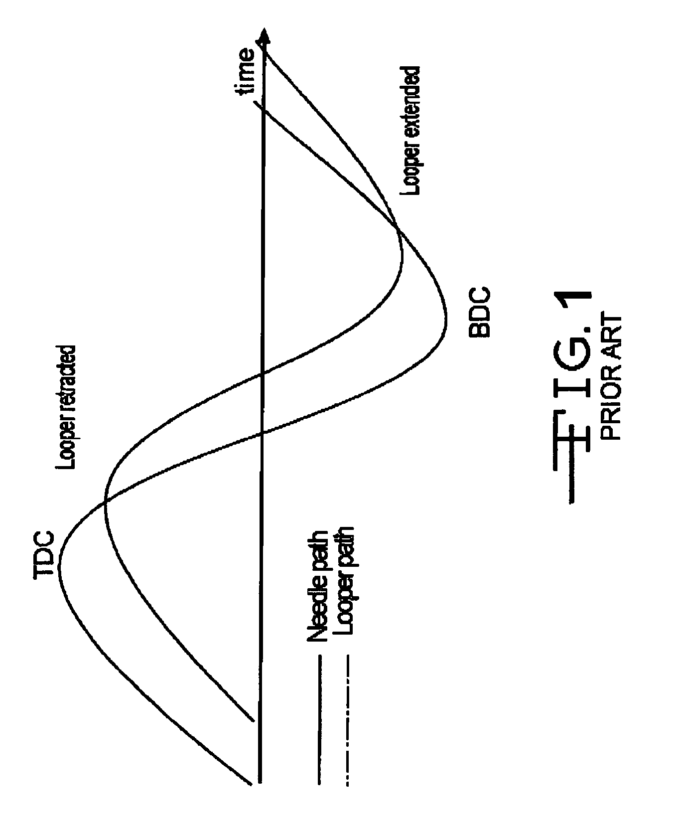
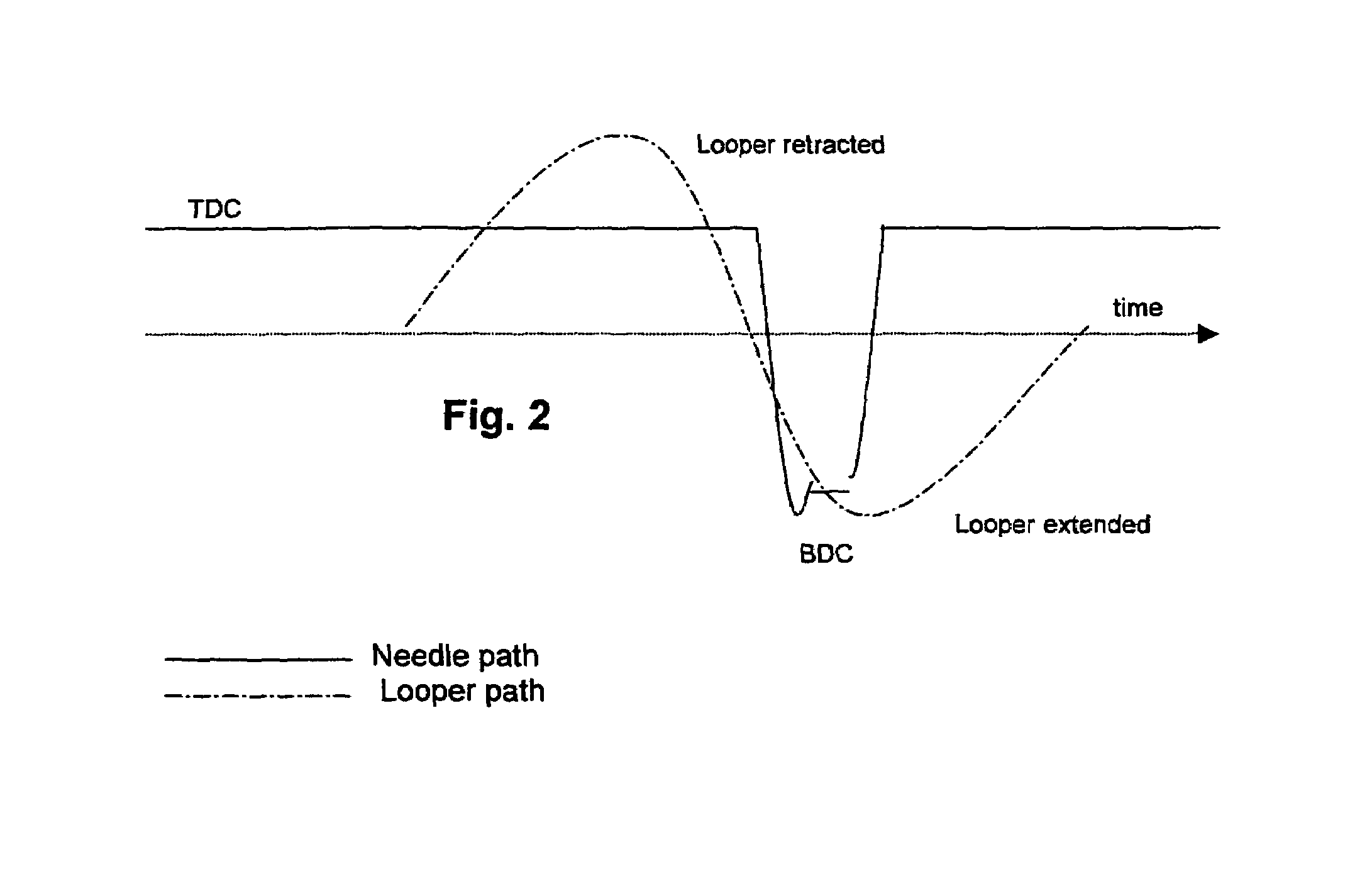
[0018]As an example, for a comparison between conventional simple harmonic needle and looper action and the non-simple harmonic needle and looper action of the present invention is shown in the accompanying drawing in which:

[0019]FIG. 1 shows conventional simple harmonic needle and looper action.

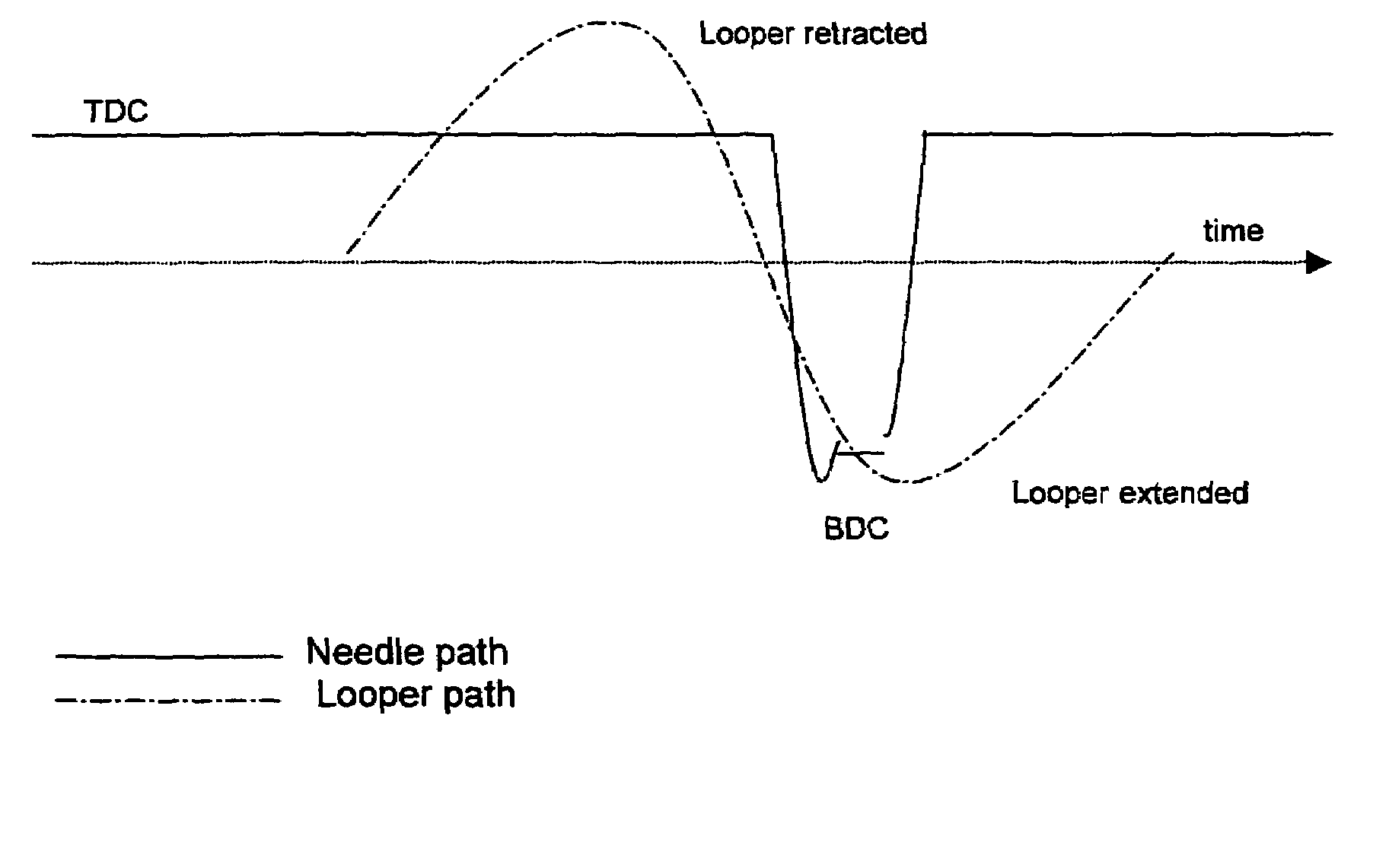
[0020]FIG. 2 shows an example of path for the non-simple harmonic motion for a needle with the (SHM) looper path shown as well.

[0021]FIG. 3 shows an example of a non-simple harmonic motion for a looper with the (SHM) needle path shown as well.

[0022]FIG. 4 shows a tufting machine.

[0023]The shown looper motions are examples and can be substituted by motions for the hooks and the knives.

[0024]Referring now to FIG. 4, a tufting machine is indicated generally at 10. The method of the present invention pertains to the operation of the tufting machine 10 or any other needlebar tufting machine. The tufting machine 10 has needles 12 and 14 which are supported by a needlebar or by needlebars, designat...


PUM


Abstract

The invention concerns a tufting machine having at least one needlebar, loopers, hooks to pick up yarn delivered through the needles of the needlebar, knives to cut yarn loops and driving means, with the needle action and / or the looper action and / or the hook action, and / or the knife action being a non-simple harmonic motion. In said machine the needles, the hooks, the knives and the loopers have separate drive systems. So the motion of the needles, the hooks, the knives and the loopers can be such that first of all the pickup of the yarn or the cutting of the yarn loop can be improved. When the drive system is computer controlled more accurate machine set up can be achieved. Moreover different set ups can be achieved automatically for different products. Patterning effects are also possible.

Description

FIELD OF THE INVENTION[0001]The invention relates to a tufting machine having at least one needlebar, loopers to pick up yarn delivered through the needles of the needlebar(s), and driving means.BACKGROUND TO THE INVENTION[0002]The action of a needlebar in a tufting machine is controlled by a main drive. Usually the drive is direct coupled and, although antivibration decoupled drive systems have evolved out of recent research to develop high speed tufters, to the best of the applicants' knowledge all needlebars follow a simple harmonic motion, oscillating between top-dead-center (TDC) and bottom-dead-center (BDC) on a regular sinusoidal path.[0003]The pick-up of yarn off of the needle, due to a looper or hook is a critical part of a tufting action which is best achieved slightly after the needle has passed BDC. Halting or slowing the needle at this point would assist the looper with respect to hook yarn pick-up.[0004]In the case of double-sliding needlebar tufters, excess top stroke...

Claims


Application Information

Patent Timeline
IPC IPC(8): D05C15/20D05C15/16D05C15/22D05C15/24
CPCD05C15/20D05C15/22D05C15/24
Inventor CLARKE, JONATHAN WILLIAMMEADE, WARREN JOHN
Owner GROZ BECKERT KG
Learn More