Balance shaft assembly

a technology of balance shaft and assembly, which is applied in the direction of mechanical equipment, rotary machine parts, machines/engines, etc., can solve the problems of out-of-balance forces and couples of three cylinder engines, cause vibration, etc., and achieve the effect of increasing the whirling frequency of the balance sha

Inactive Publication Date: 2005-12-06
PERKINS ENGINES
View PDF7 Cites 11 Cited by
  • Summary
  • Abstract
  • Description
  • Claims
  • Application Information

AI Technical Summary

Benefits of technology

[0017]The invention also provides a method of loading a bearing in a balance shaft assembly comprising the steps of forming an elongate housing having a front end and a rear end; mounting a front end bearing, a rear end bearing and an intermediate bearing in the housing; rotatably supporting a balance shaft between the front end bearing, the intermediate bearing and the rear end bearing; and causing the intermediate bearing to become aligned with the front end and rear end bearings by latera

Problems solved by technology

If the inertia force of the moving pistons is not balanced, then vibration is caused, acting on the engine in the direction of travel of the pistons.
The resultant vibration may be undesirable, particularly in mobile vehicles into which the engine may be fitted.
Three cylinder engines also suffer from the aforementioned engine out-of-balance forces and couples.
Location of the balance shaft in the sump can result in aeration of oil in the sump and increased oil temperature.
Known balance shaft assemblies are also limited in the length of balance shaft which can be employed due to constructional limitations thereby limiting

Method used


Image

  • Balance shaft assembly
  • Balance shaft assembly

Examples


Embodiment Construction

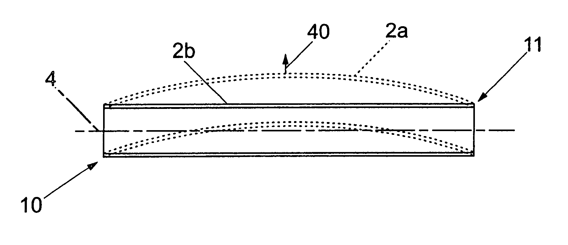
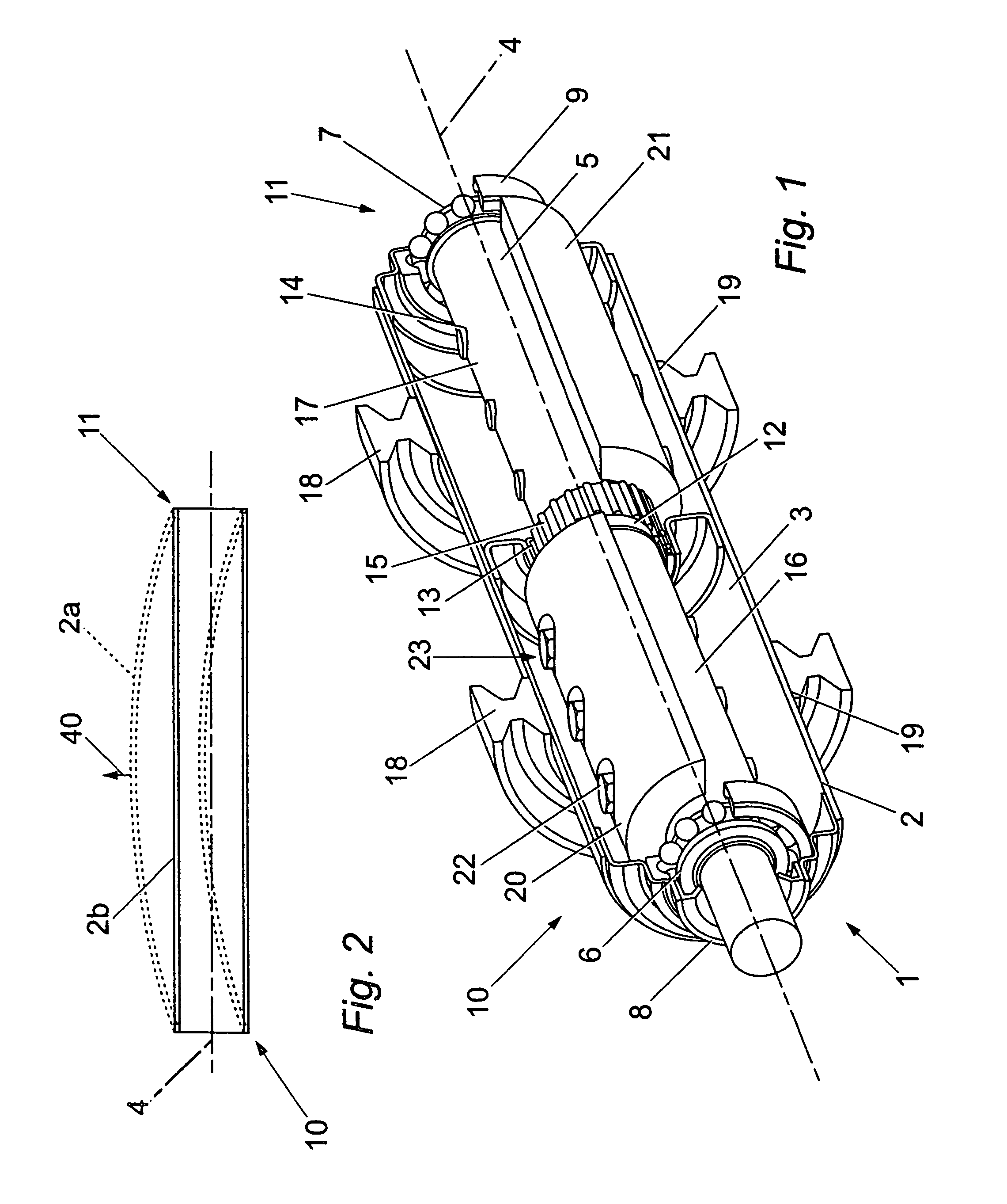
[0021]As shown in FIG. 1, a self-contained balance shaft assembly in accordance with the invention is generally indicated by the reference numeral 1 and includes a self-contained tubular (elongate) housing 2 having a side-wall 3 and a central longitudinal axis 4. The housing 2 houses a rigid balance shaft 5 and is preferably formed from a steel tube, as an aluminium extrusion or as a plastics pultrusion. The housing 2 is formed of any suitable material that allows it to be at least partially flexible in a transverse direction 40 with respect to the balance shaft 5, as shown in FIG. 2, such that the housing is free to adopt a deflected shape 2a or an undeflected shape 2b. The flexibility of the housing 2 is selected so that the housing 2 is just sufficient to damp the balance shaft 5 whirling tendency.

[0022]In the present embodiment, a primary self-contained balance shaft assembly for a three cylinder engine is described. However, as will be appreciated by those skilled in the art, t...


PUM

PropertyMeasurementUnit
Forceaaaaaaaaaa
Flexibilityaaaaaaaaaa
Stiffnessaaaaaaaaaa

Abstract

Balance shaft assemblies are used in internal combustion engines to dampen primary and second order inertia forces. Known balance shaft assemblies typically require precision manufacturing and a rigid frame or housing. A balance shaft assembly (1) in accordance with this invention provides a low cost and less complex solution to engine balancing. The balance shaft assembly (1) includes an elongate housing (2) having a front end and a rear end, a balance shaft (5) which is rotatably supported between a front end bearing (6), a rear end bearing (7) and an intermediate bearing (12) in the housing (2). The housing (2) is transversely flexible relative to the balance shaft (5) to accommodate misalignment of the intermediate bearing (12) relative to the front and rear end bearings (6, 7). Consequently, the balance shaft assembly (1) can be less complicated and manufactured at a lower cost than known balance shaft assemblies.

Description

TECHNICAL FIELD[0001]This invention relates to a balance shaft assembly and to an engine including the balance shaft assembly.BACKGROUND[0002]In mobile machines, vehicle excitations are created from engine out-of-balance forces and couples (moments) generated by the rotating and reciprocating engine component masses.[0003]In an in-line four-cylinder engine, for example, as the pistons reciprocate within the cylinders an inertia force is created by the reciprocating movement of each piston. If the inertia force of the moving pistons is not balanced, then vibration is caused, acting on the engine in the direction of travel of the pistons. The resultant vibration may be undesirable, particularly in mobile vehicles into which the engine may be fitted.[0004]It is known to counterbalance the inertia forces of the pistons using one or more balance shafts. The or each balance shaft is typically located in the sump of an engine and suspended beneath the crankshaft. In in-line four cylinder e...

Claims


Application Information

Patent Timeline
IPC IPC(8): F02B67/06F16F15/26
CPCF02B67/06F16F15/264Y10T29/49696Y10T464/50
Inventor LAWRENCE, HOWARD J.
Owner PERKINS ENGINES
Why Eureka
Try Eureka