Pump for dispensing flowable material

a technology of flowable materials and pumping equipment, which is applied in the direction of positive displacement liquid engines, pumping pumps, pliable tubular containers, etc., can solve the problems of increasing production costs, increasing assembly costs, and limited amount of material which may be dispensed, and achieves a higher dosage pump and a smaller “footprint. ), the effect of increasing the efficiency

Inactive Publication Date: 2005-12-06
BRENNAN JAMES WILLIAM +1
View PDF12 Cites 102 Cited by
  • Summary
  • Abstract
  • Description
  • Claims
  • Application Information

AI Technical Summary

Benefits of technology

[0008]a pump body deformable between a rest configuration and a squeezed configuration, the internal capacity of the pump body being substantially reduced in the squeezed configuration compared to the rest configuration;
[0020]In a further preferred embodiment the pump body is formed with a bellows section which is symmetrical about the vertical plane, but is shaped in a way to provide an asymmetrical aspect when viewed from the front and the rear. The head can be activated from either side or from both sides, therefore increasing its efficiency (creating a higher dosage pump on a smaller “footprint”).
[0021]The asymmetry does this as the head is activated the tension and length of the surface skin “subtly” unloads the nozzle tips. This allows the material to dispense more easily. The pressure inside the chamber seals the upper end of the void (conventional flap valves), and forces the expansion of the head in the nozzle area. As the limit of the stroke is reached the pressure equalises and the nozzle seals itself again. This causes the chamber to open again and draw material back in the fill the void preparing the pump for the next stroke.
[0022]The cross-section of the part can be either elliptical or circular, and its ease of manufacture means it can be put up to a variety of configurations. The efficacy of the valve means that a diverse range of materials can be applied from orange juice, paints, gels, antiseptic liquids etc.
[0023]The present invention provides advantages in terms of cost efficiency, ability to eliminate contamination and cross-infection, and the control of inventory of materials.

Problems solved by technology

A disadvantage with this type of pump is the limited amount of material which may be dispensed with a single depression of the plunger.
Whilst this problem may be overcome by increasing the size of the assembly, the plunger and its associated hardware must be rigid enough to resist the forces acting upon them, which in turn increases production costs.
Similarly, the container itself must be rigid, as must the connection between the pump and the container, which can lead to the assembly being relatively expensive.
However, the mountings and the container itself must still be rigid, which again leads to additional cost.
The relatively expensive nature of such prior art pumping systems has meant that they are generally not incorporated into disposable items.
Unfortunately, particularly in environments where hygiene is essential such as surgeries and the like, the build-up of dirt and bacteria around those components of the pump which come into contact with the surrounding environment and human hands can prove problematic.
Whilst these non-disposable components may periodically be cleaned and sanitised, this is a time consuming job which is often not undertaken on a sufficiently regular or thorough basis.

Method used


Image

  • Pump for dispensing flowable material
  • Pump for dispensing flowable material
  • Pump for dispensing flowable material

Examples


Embodiment Construction

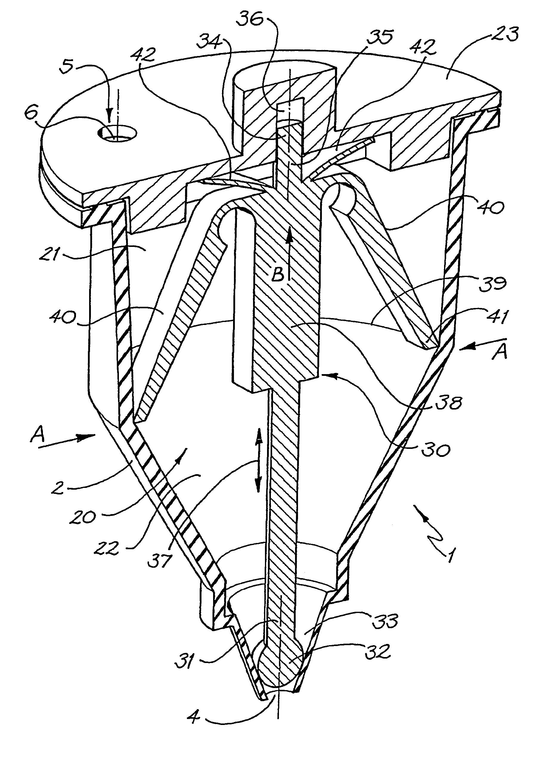
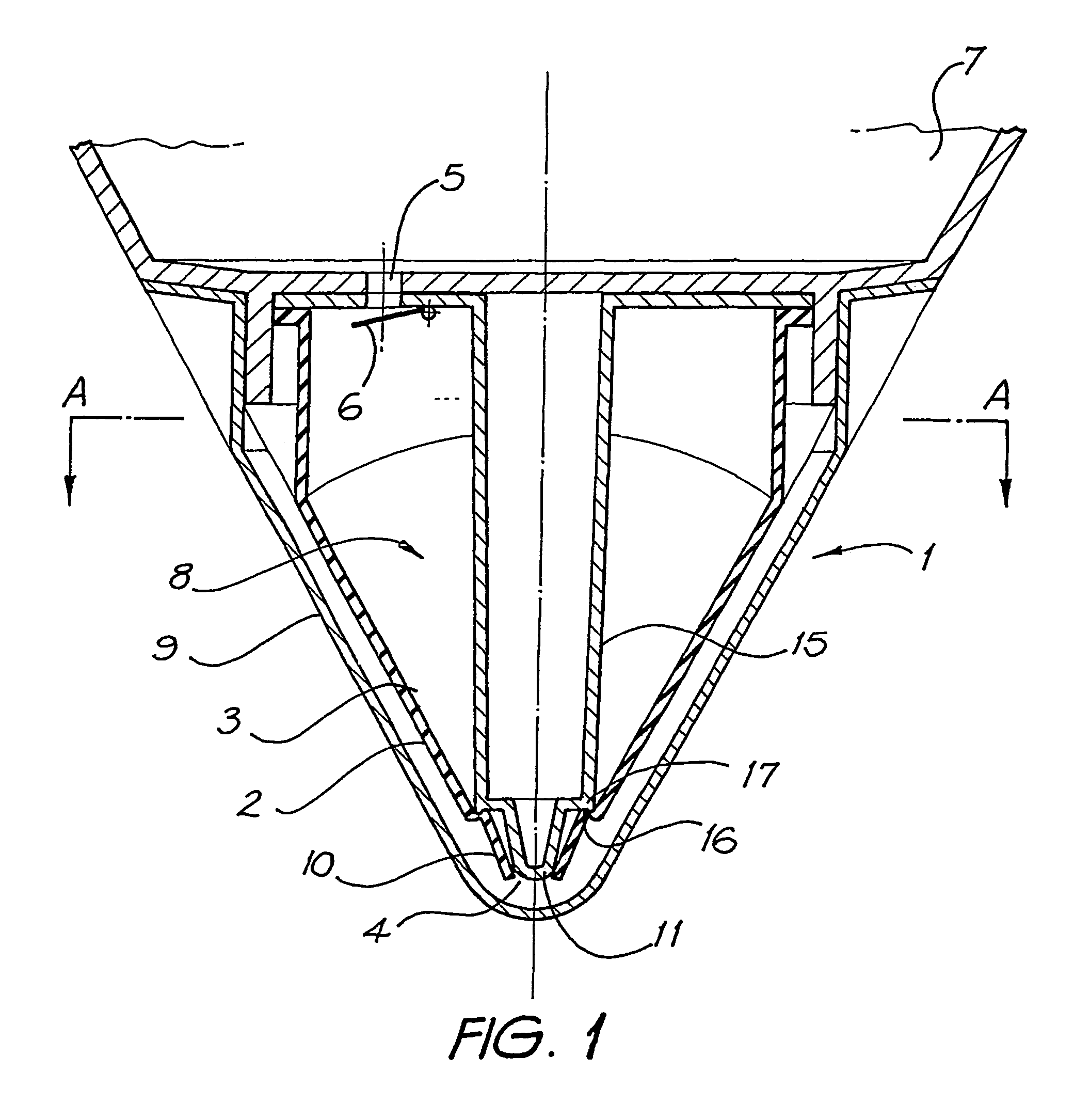
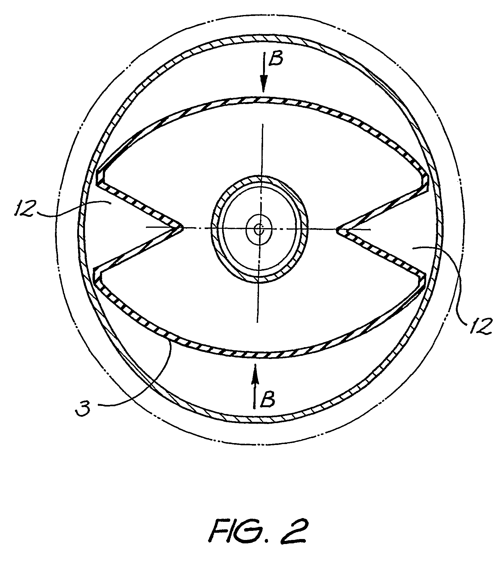
[0035]Referring to FIGS. 1 and 2 of the accompanying drawings, a preferred embodiment of the dispensing device according to the present invention is depicted. The pump 1 includes a pump body 2 formed by a flexible walled member 3. The pump includes an outlet 4 from which flowable material is dispensed and an inlet 5 which is controlled by a unidirectional valve 6. The material to be dispensed flows through the inlet 5 via the valve 6 from a reservoir (not shown) positioned in region 7.

[0036]When closed, the flap valve 6 seals the orifice 5 to prevent the reverse flow of material from the pump chamber 8 back into the reservoir 7. In FIG. 1, the pump is depicted with a removable cap or cover 9 fitted over the outlet and walls of the pump body.

[0037]The pump body 2 includes a nozzle section 10 which is formed as a flexible funnel with a relatively low ramp angle and terminating with the outlet 4. The pump further includes a relatively rigid internal member 15 which lies on the longitud...


PUM


Abstract

The invention relates to a dispensing device which can be used to dispense a metered volume of a flowable material such as a liquid, gel or paste product from a reservoir. The invention provides a pump for dispensing a flowable material from a container, the pump including a pump body which is deformable between a rest configuration and a squeezed configuration, the internal capacity of the pump body being substantially reduced in the squeezed configuration compared to the rest configuration.

Description

FIELD OF THE INVENTION[0001]The present invention relates to dispensing apparatus for dispensing a flowable material from a reservoir. More particularly, the invention relates to a dispensing device which can be used to dispense a metered volume of a flowable material such as a liquid, gel or paste product from a reservoir.BACKGROUND OF THE INVENTION[0002]A number of pumps for dispensing a flowable material from a reservoir are currently known. One common type is a positive displacement pump which generally comprises a spout mounted atop a hollow plunger assembly which extends downwardly into a complementary cylinder. In order to dispense a volume of material the user places one hand under the spout and depresses the plunger with the other hand. By means of various valves, depressing the plunger causes the flowable material to be dispensed from the spout. The plunger is spring loaded so that it returns to its original position upon release, whilst refilling the cylinder in readiness...

Claims


Application Information

Patent Timeline
Patent Type & Authority Patents(United States)
IPC IPC(8): B05B11/00B65D35/28B65D47/34B65D83/00B65D85/72F04B9/14F04B43/08
CPCB05B11/0059B05B11/0075B05B11/3032B05B11/3053B05B11/3077F04B9/14F04B43/08B05B11/1032B05B11/1053B05B11/1077
Inventor BRENNAN, JAMES WILLIAMBREWER, PETER RUSSELL
Owner BRENNAN JAMES WILLIAM
Why Eureka
Try Eureka