Bumper system with "W" beam and energy absorber

a bumper system and beam technology, applied in the field of bumper systems, can solve the problems of slow rollforming process, inconvenient assembly, and inconvenient assembly of tubular bumper beams, and achieve the effects of reducing assembly time and cost, reducing weight, and being easy to make and secure together

Inactive Publication Date: 2005-12-06
NETSHAPE INT LLC
View PDF15 Cites 42 Cited by
  • Summary
  • Abstract
  • Description
  • Claims
  • Application Information

AI Technical Summary

Benefits of technology

[0011]Advantageously, the present arrangement is lightweight, since the straps are minimal in weight, and yet the beam is strong, since the straps connect the horizontal walls of the beam together to prevent premature failure of the beam upon front impact. The components of the assembly are relatively easily made and secured together, such that assembly time and cost is minimized. Advantageously, the beam is stable even if impacted at an angle, due to the diagonal “truss-like” stability created by the diagonal straps. The energy-absorbing sections of the energy absorber that extend into the beam create additional stability. Further, the sequence caused upon a frontal impact results in a very predictable, stable, reliable crush, and results in excellent energy absorption and communication of controlled amounts of stress through the bumper system to the vehicle frame.

Problems solved by technology

However, tubular bumper beams are not inexpensive.
For example, tubular bumper beams must be welded along a continuous strip extending a full length of the beam, which costs money, time, and material; requires substantial investment in welding equipment; can slow a rollforming process down; and can lead to heat-related distortions and non-uniformities resulting in non-linear beam shapes.
One problem of non-tubular beams is that their flanges tend to spread apart during an impact, such that their beam strength is quickly lost due to kinking and premature bending.

Method used


Image

  • Bumper system with "W" beam and energy absorber
  • Bumper system with "W" beam and energy absorber
  • Bumper system with "W" beam and energy absorber

Examples


Embodiment Construction

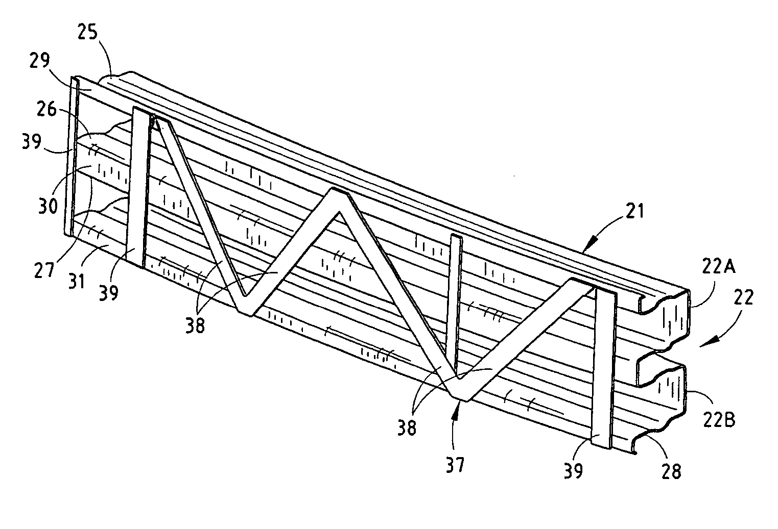
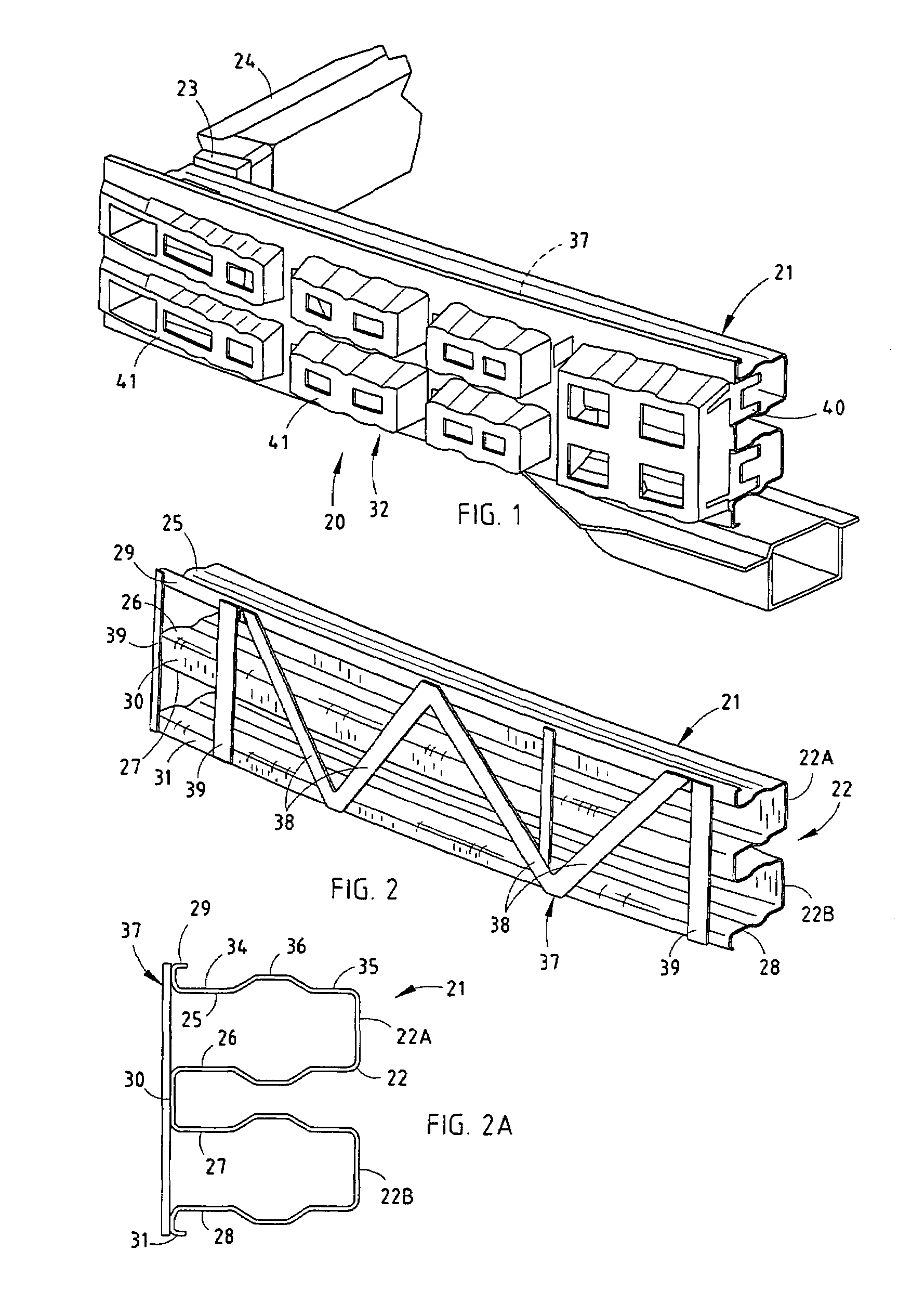
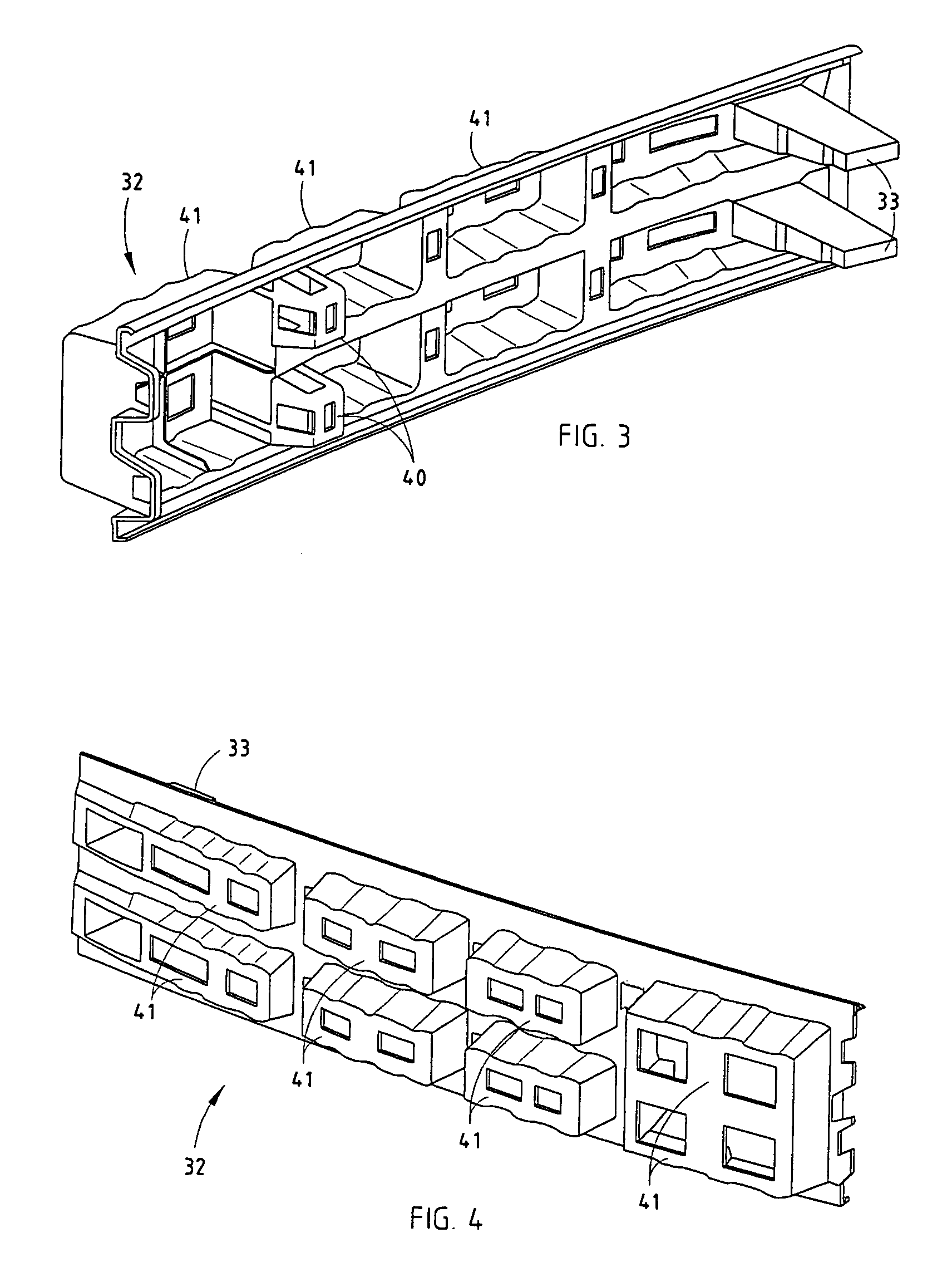
[0018]A bumper system 20 (FIG. 1) combines a rollformed metal W-shaped beam 21, a stamped metal brace 37 welded to an open side of beam 21, and a polymeric energy absorber 32 to form a novel energy absorbing system having reduced weight, reduced manufacturing cost, and excellent energy absorption, as described below.

[0019]The W-shaped beam 21 has a back wall 22 formed by back sections 22A and 22B, and has mounts 23 along the back wall 22 adapted for attaching the beam 21 to rails 24 of a vehicle frame. The beam 21 also includes four forwardly-extending horizontal parallel walls 25–28, and a face formed by front walls 29–31. The front walls 29–31 provide sufficient frontal surface area to satisfactorily engage and support the energy absorber 32, as shown in FIG. 1. The energy absorber 32 engages the face of the beam 21 and has rearwardly-extending energy-absorbing end sections 33 that extend through the face into contact with the back wall 22 at each of the mounts 23 (i.e. at ends of...


PUM


Abstract

A bumper system includes a “W” or “C” shaped beam having a back wall and mounts along the back wall adapted for attaching the beam to rails of a vehicle frame. An energy absorber engages a face of the beam and has rearwardly-extending energy-absorbing sections that extend through the face into contact with the back wall at each of the mounts for improved energy absorption. The horizontal walls of the beam have front and rear sections that align, but also have a U-shaped intermediate section that weakens the walls for promoting a more uniform and predictable collapse. A one-piece brace includes diagonal straps that hold free ends of top and bottom walls together to prevent premature spreading apart upon impact. The energy absorber includes energy-absorbing sections that extend past the straps to detentingly engage the intermediate sections of the beam.

Description

CROSS-REFERENCE TO RELATED APPLICATIONS[0001]This application claims benefit of provisional application Ser. No. 60 / 479,623, filed Jun. 18, 2003, entitled BUMPER SYSTEM WITH “W” BEAM AND ENERGY ABSORBER.BACKGROUND[0002]The present invention relates to bumper systems, and more particularly relates to a bumper system including a beam and energy absorber components for optimally absorbing energy during a vehicle impact. The illustrated beam has a “W” shaped cross section, but the present concepts are not believed to be limited to only a “W” section.[0003]It is desirable to provide a bumper system that optimally manages energy absorption by providing for maximum energy absorption during a vehicle crash, yet that does so without overloading the vehicle's frame. Managing energy at the bumper-to-vehicle-frame mounts is especially critical, since this is the area where loads are communicated to the vehicle's frame during a crash. However, the beam must also not prematurely kink or unpredict...

Claims


Application Information

Patent Timeline
Patent Type & Authority Patents(United States)
IPC IPC(8): B60R19/18
CPCB60R19/18B60R2019/1826B60R2019/188
Inventor EVANS, DARINJOHNSON, THOMAS J.DORNBOS, ROBERT J.WHITE, MARK P.
Owner NETSHAPE INT LLC
Why Eureka
Try Eureka