Ultrasonic imaging method and apparatus

a technology of ultrasonic imaging and apparatus, applied in the field of ultrasonic probes, can solve the problems of preventing the attainment of sufficient image quality, receiving signals, and long processing time of proposed methods, and achieves the effects of high implementation cost, easy implementation, and high complexity of apparatus

Active Publication Date: 2005-12-06
ESAOTE
View PDF6 Cites 10 Cited by
  • Summary
  • Abstract
  • Description
  • Claims
  • Application Information

AI Technical Summary

Benefits of technology

[0043]Total defocusing for transmission and second harmonic focusing for signal reception according to the method of this invention, allow all ultrasonic energy transmission energy to be averaged.
[0044]This provides an additional advantage with respect to conventional averaging methods, wherein imaging is performed by successively focusing transmit beams on a point, a line or a limited region of the subject under examination. Here the mean of a predetermined number of scans along the same line requires the ultrasonic energy, focused on said point, line or limited region, to be transmitted for a number of times corresponding to the predetermined number of scans to be averaged. The method of the invention provides useful data for averaging all lines for each transmission cycle. Considering a scan with n lines, in order to obtain the mean of m detection samples along the same line, the method of the invention allows to only execute m transmission and reception cycles, whereas the conventional method requires the execution of m scans, i.e. m ultrasonic wave transmission and reception cycles, for each of the n scan lines.
[0052]As is apparent, the apparatus of the invention requires no considerable change to the hardware of conventional ultrasonic imaging apparatuses, excepting the provision of a memory for each receiving channel and means for determining write and read addresses. Nevertheless, it shall be noted that, as each address corresponds to the depth of that sampled part of the received signal, the means for determining the write address simply consist of depth meters. Also, these means automatically provide a part that is necessary for determining the read address of the memory, the other part thereof being provided, like in existing apparatuses, by the received beam focusing means, which impart the delays required for focusing received signals on a predetermined point, line or limited region of the subject under examination.
[0053]As far as construction is concerned, the method and the apparatus of the invention only require small construction changes which do not involve a higher complexity of the apparatus, and do not require high implementation costs.
[0054]It shall be further noted that, due to the above considerations, the method of the invention may be rather easily implemented in existing apparatuses and does not restrict or prevent the possibility of using, as an alternative to the inventive method, well-known and conventional ultrasonic imaging methods, which also provide higher or lower transmit beam focusing.

Problems solved by technology

The proposed methods require a long processing time and complex hardware.
The above mentioned defocusing process, as well as the use of the fundamental transmission frequency component of the received signal, cause the secondary lobes to strongly affect the received signals and to prevent the attainment of a sufficient image quality.
Current transmitted beam defocusing techniques do not allow to reach sufficient image definition and resolution levels.
Current problems are the sensitivity limit caused by the use of low mechanical pressures (aimed at not breaking contrast agents) and tissue residual components due to the incomplete removal of non linearities of the ultrasonic imaging system, especially upon transmission.
All the methods and apparatuses described therein are relatively complex, and cause ultrasonic imaging apparatuses to be complex and expensive.
Particularly for convex probes, but in extreme cases even for linear probes, the limitation of the ultrasound beam to a portion of the region that may be examined by the whole array of transmitting transducers, i.e. only to a few scan lines, allows to obviate a few drawbacks associated to the need of imparting too long delays to the transmitting transducers that are arranged in such positions as to form a very wide angle of incidence on the examined region.

Method used


Image

  • Ultrasonic imaging method and apparatus
  • Ultrasonic imaging method and apparatus
  • Ultrasonic imaging method and apparatus

Examples


Embodiment Construction

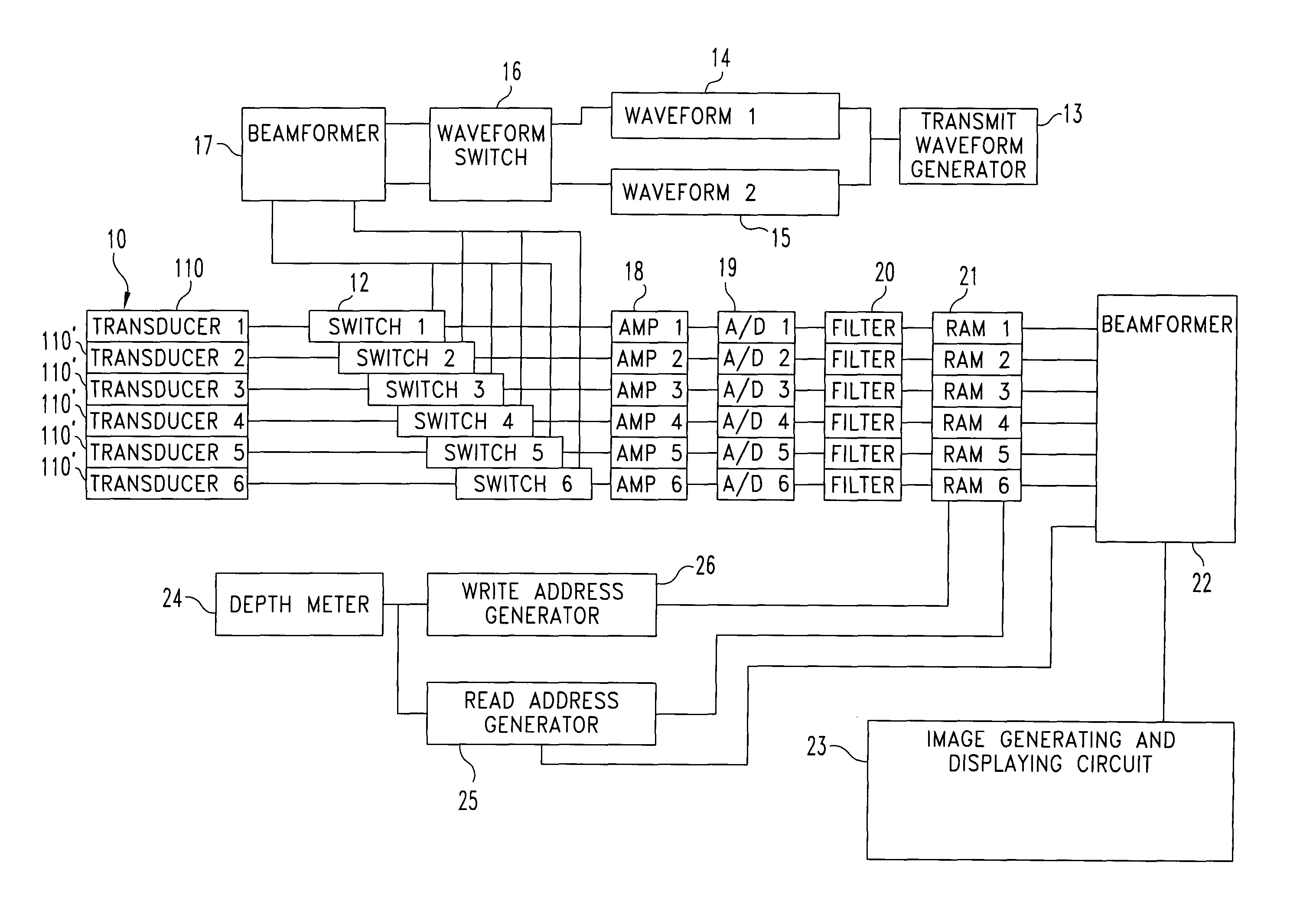
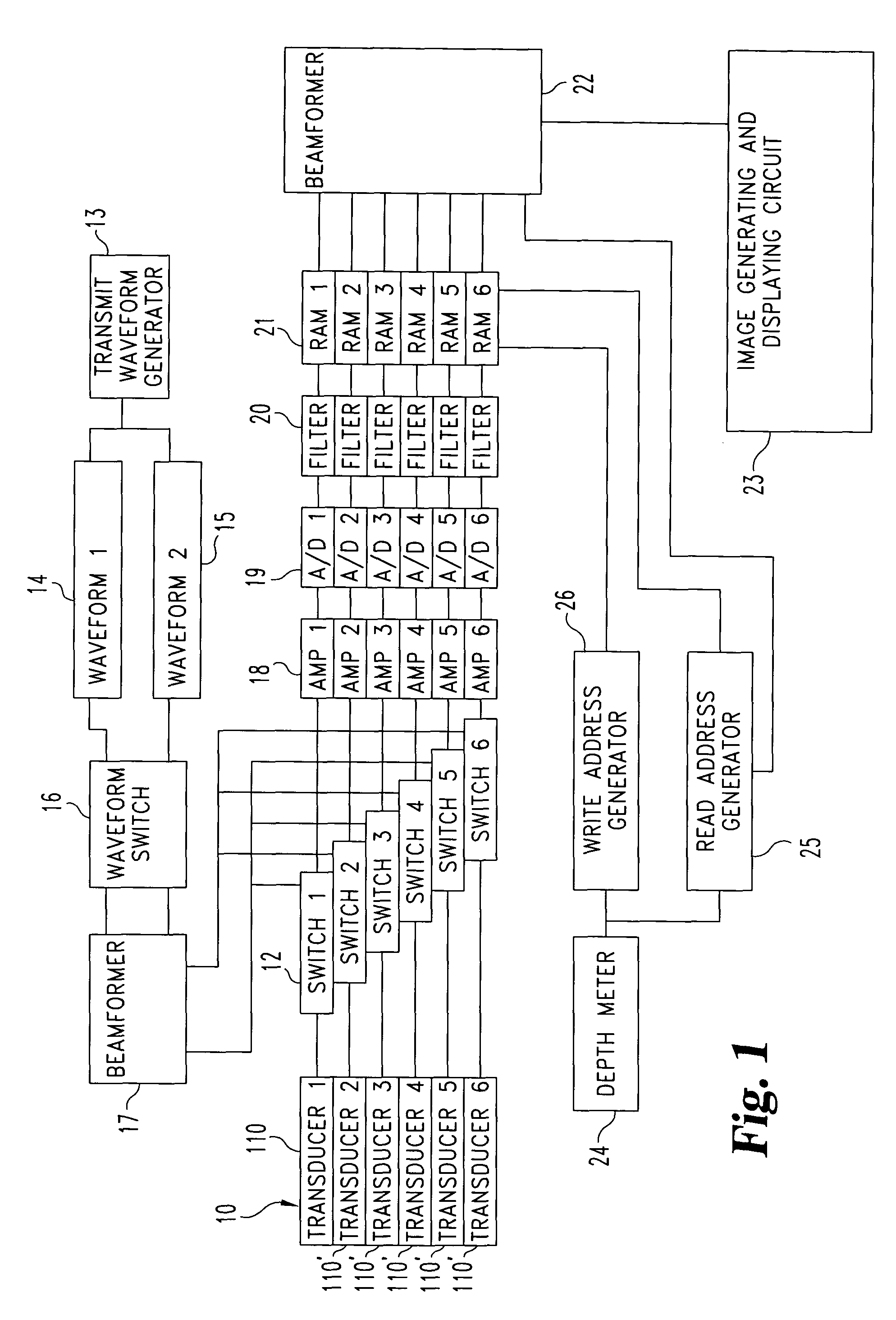
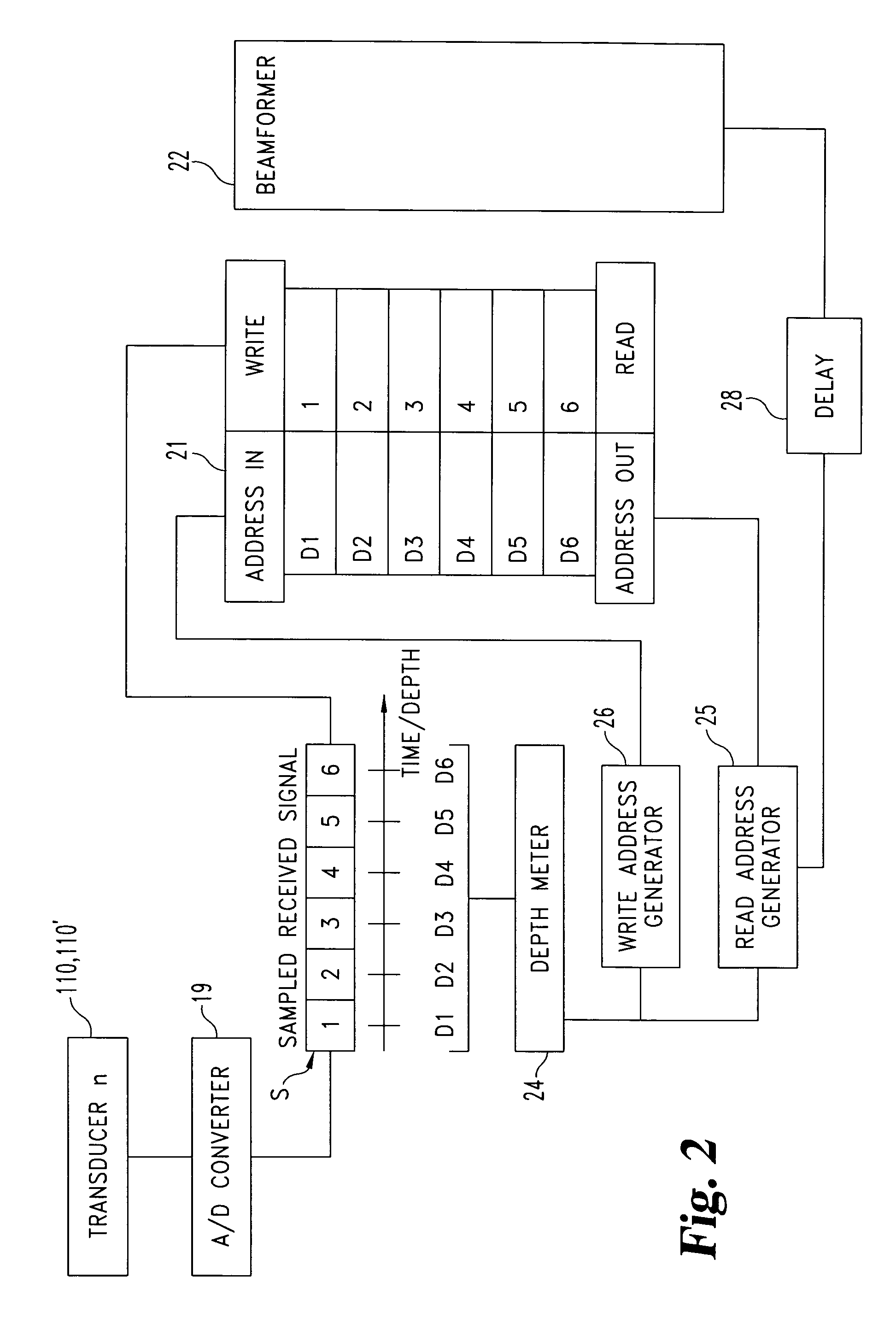
[0059]Referring to FIG. 1, an ultrasonic imaging apparatus includes a probe 10 composed of a plurality of transducers 110. For the sake of simplicity, the figure only shows six electroacoustic transducers, forming a linear array. Nevertheless, it shall be noted that the invention is not limited to the linear array probe, but may be also applied to other types of probes.

[0060]The individual transducers 110 are diversified by numbering them from 1 to 6. Typically, linear array probes have 64 to 256 electroacoustic transducers, acting as transmitting and receiving transducers. Each transducer is connected to a switch 12 which alternately connect them to an ultrasonic wave generating signal supply and to the receiving circuit.

[0061]The transducer transmission actuating signal is provided by a generator 13 which supplies two waveformers 14 and 15. The signal consists of a pulse having a predetermined duration and a predetermined frequency, which will cause the generation of an ultrasonic...


PUM


Abstract

An ultrasonic imaging method and apparatus wherein the ultrasonic energy transmitted to a subject under examination is generated by a plurality of electroacoustic transducers, which are actuated for transmission with predetermined delays according to a predetermined focusing rule; the ultrasonic energy reflected by the subject under examination is received by an array of electroacoustic transducers which are actuated to read received signals with predetermined delays according to a received signal focusing rule. The focused received signals are turned into image data for ultrasonic image display. The transmitting transducers are actuated with such delays as to generate a homogeneous acoustic field over all or part of the region of the subject under examination.

Description

[0001]The invention relates to an ultrasonic imaging method and apparatus, and in particular, to an ultrasonic imaging method and apparatus using multiple transducers.CROSS-REFERENCE TO RELATED APPLICATION[0002]The present application claims priority of Italian Patent Application Serial No. SV2002A000040 filed Aug. 13, 2002, which is hereby incorporated by reference in its entirety.BACKGROUND[0003]In prior art, ultrasonic probes have a plurality of electroacoustic transducers which are alternately actuated either for transmission or for reception. Imaging is performed, for instance, by scanning slice planes. In ultrasound imaging, a wavefront is transmitted to a subject and the reflected wavefront is detected. The reflected signals obviously contain information about the reflection centers or fronts. The information contained in the reflected wave may be extracted and processed to reconstruct images from reflected fronts. The amplitude variations of the reflected wave allow to assig...

Claims


Application Information

Patent Timeline
Patent Type & Authority Patents(United States)
IPC IPC(8): G01S7/52G01S15/89G10K11/34
CPCG01S7/52038G01S15/8927G01S15/8959G01S15/8963G10K11/346G01S7/52046G01S15/8961
Inventor CEROFOLINI, MARINO
Owner ESAOTE
Why Eureka
Try Eureka