Data storage card having both linear and annular data regions

a data storage card and linear technology, applied in the field of card-type devices, can solve the problems of credit cards in their current state, impede their ability to be used for more sophisticated purposes, and insufficient magnetic stripe alone to store large amounts of data, so as to reduce the chance of the card getting stuck therein

Inactive Publication Date: 2006-07-25
BERKLEY JON +1
View PDF9 Cites 9 Cited by
  • Summary
  • Abstract
  • Description
  • Claims
  • Application Information

AI Technical Summary

Benefits of technology

[0019]In accordance with the present invention, there is provided a data storage card having optical and magnetic data storage regions. The card is formed to cooperatively engage both a drive mechanism of a magnetic stripe reader and a drive mechanism of an optical data reader. The card includes a card body with a first and second opposed generally planar surfaces. The card also includes at least one annular optical data storage region disposed on one or both of the first and second surfaces of the card body. Moreover, the card includes at least one magnetic linear data storage region disposed on one or both of the first and second surfaces. Additionally, the card includes an optical carriage engaging aperture formed in the card bo

Problems solved by technology

However, credit cards in their current state have a severe limitation which impedes their ability to be used for more sophisticated purposes.
However, the magnetic stripe alone is insufficient to store large amounts of data.
Non-annular optical data regions and optical strips are typically composed of the similar types of material, yet can be less efficient than annular optical data regions.
Existing cards which utilize on-annular optical regions or strips have severely limited data transfer rates due to the excessive amount of time that is typically required to read data from the optical strip.
Additionally, allowing the data to be stored on the access card itself lifts an enormous burden off the system resources of access card readers, which would otherwise be required to store such large amounts of data internally.
Such an access card reader capable of reading a high capacity data storage card may then be distributed in areas of the world where an access card reader may otherwise be too expensive to maintain, such as third world countries.
Although adding an optical region or optical strip is advantageous due to the increased data capacity, the read/write apparatus may be costly and difficult to integrate into a current marketplace that may be less responsive to integrating a new technology.
Existing card readers might need to be updated with a specialized apparatus, causing a higher expenditure for those who wish to integrate the card and a burden on consumers who are unfamiliar with the technology.
Such CD-writers could potentially be used for the purpose of reading and writing data to annular optical data regions whereas optical strips may not be compatible with conventional CD-writers, and may require a specialized apparatus or manufacturing process to read and write data.
Integrating both a magnetic stripe and an annular optical data re

Method used


Image

  • Data storage card having both linear and annular data regions
  • Data storage card having both linear and annular data regions
  • Data storage card having both linear and annular data regions

Examples


second embodiment

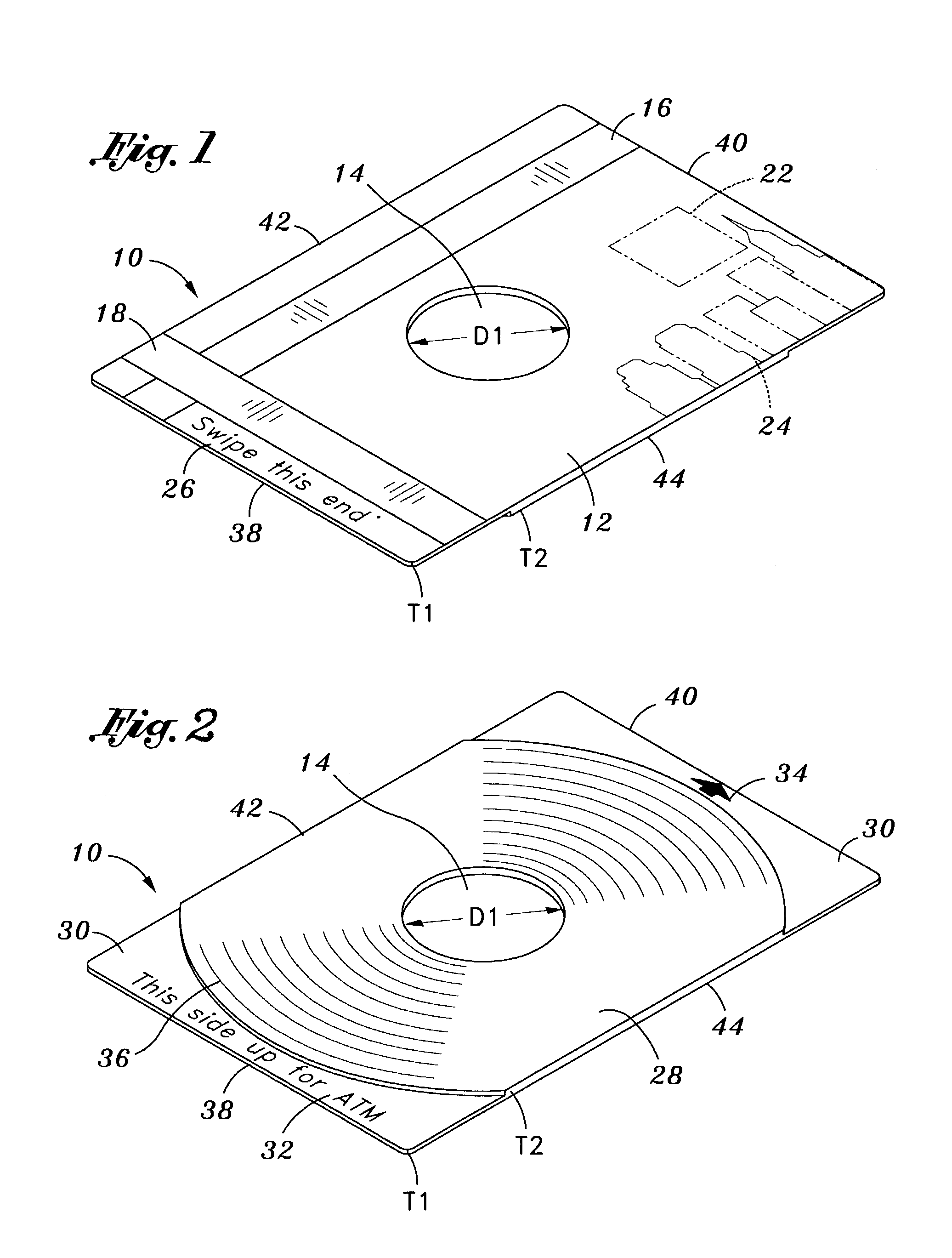
[0083]Referring now to FIGS. 4 and 5, an annular optical data region 28 is preferably disposed on the second planar surface 30. A cross-sectional profile of the card body 10 taken along one of the first and second lateral edges 42 and 44 depicts the truncated conical raised portion of the card body 10. Contemporary optical drive carriages are constructed with a circular recessed groove made to fit 3 inch optical discs (not shown). Thus, a portion of the second planar surface 30 should be constructed with at least one physical step which allows the card body 10 to fit snugly into the recessed groove of an optical drive's carriage. In the second embodiment, the entire optical annular data region 28 is raised to complement the optical drive carriage's recessed groove. Precise alignment of the disc with the recessed grooves ensures that the optical drive properly mounts to the disc to read the optical track 36.

[0084]Referring now to FIGS. 2 and 5, the annular optical data region 28 disp...

fifth embodiment

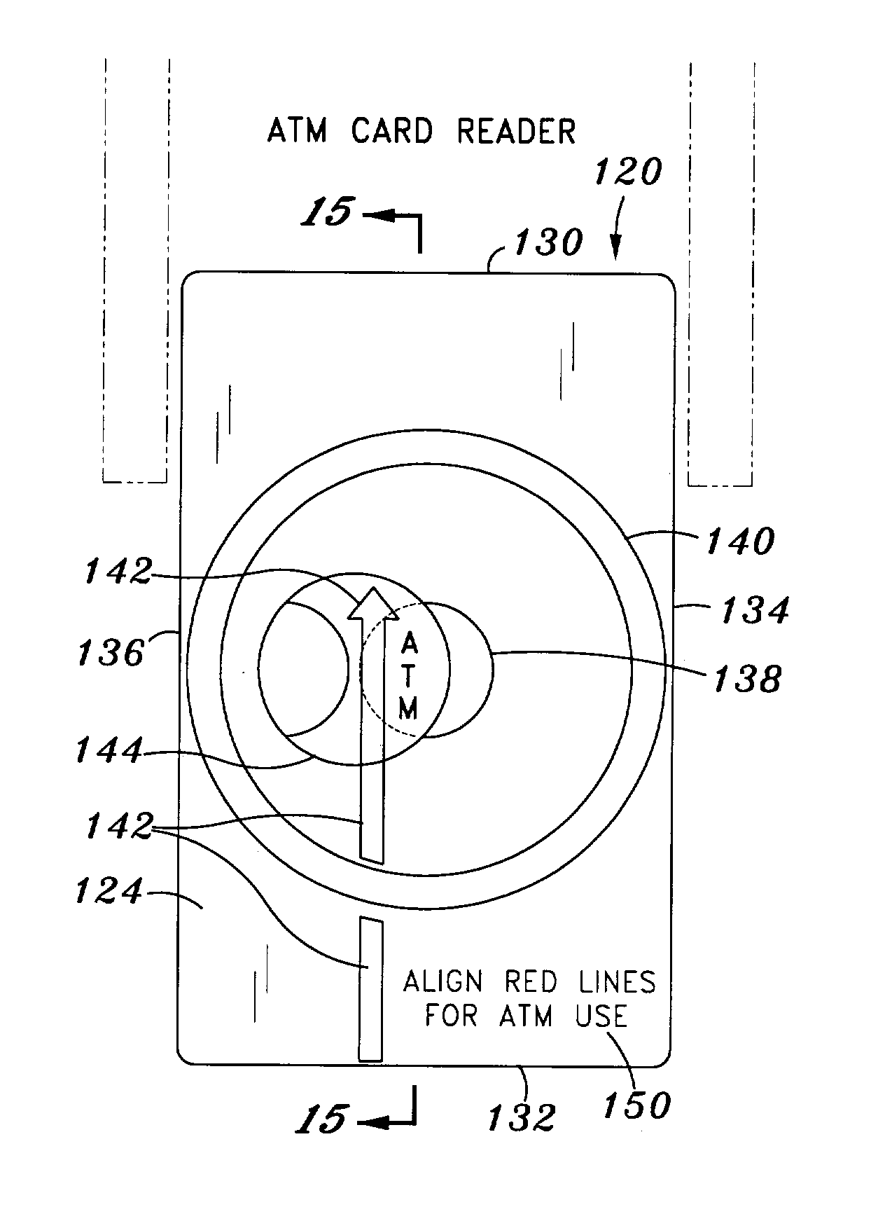
[0097]Referring now to FIGS. 16–18, the data storage card made according to the present invention is shown. As shown in FIG. 18, the card body 120 with the aperture sheath 144 in the first position for cooperatively engaging the card body 120 with the rotatable spindle of an optical drive carriage 156 may be inserted into the grooves 158 of the optical drive carriage 156. The aperture sheath 144 may be movable between a first position raised above one of the first and second planar surfaces 122 and 124 and a second position substantially coplanar with one of the first and second planar surfaces 122 and 124. As shown in FIG. 17, when the aperture sheath 144 is in the first position, the aperture sheath may be raised above the first planar surface 122. In this respect, raising the aperture sheath 144 prevents the card body 120 from being mistakenly inserted into an ATM machine. By lowering the aperture sheath 144 into the second position substantially coplanar with the first planar su...

ninth embodiment

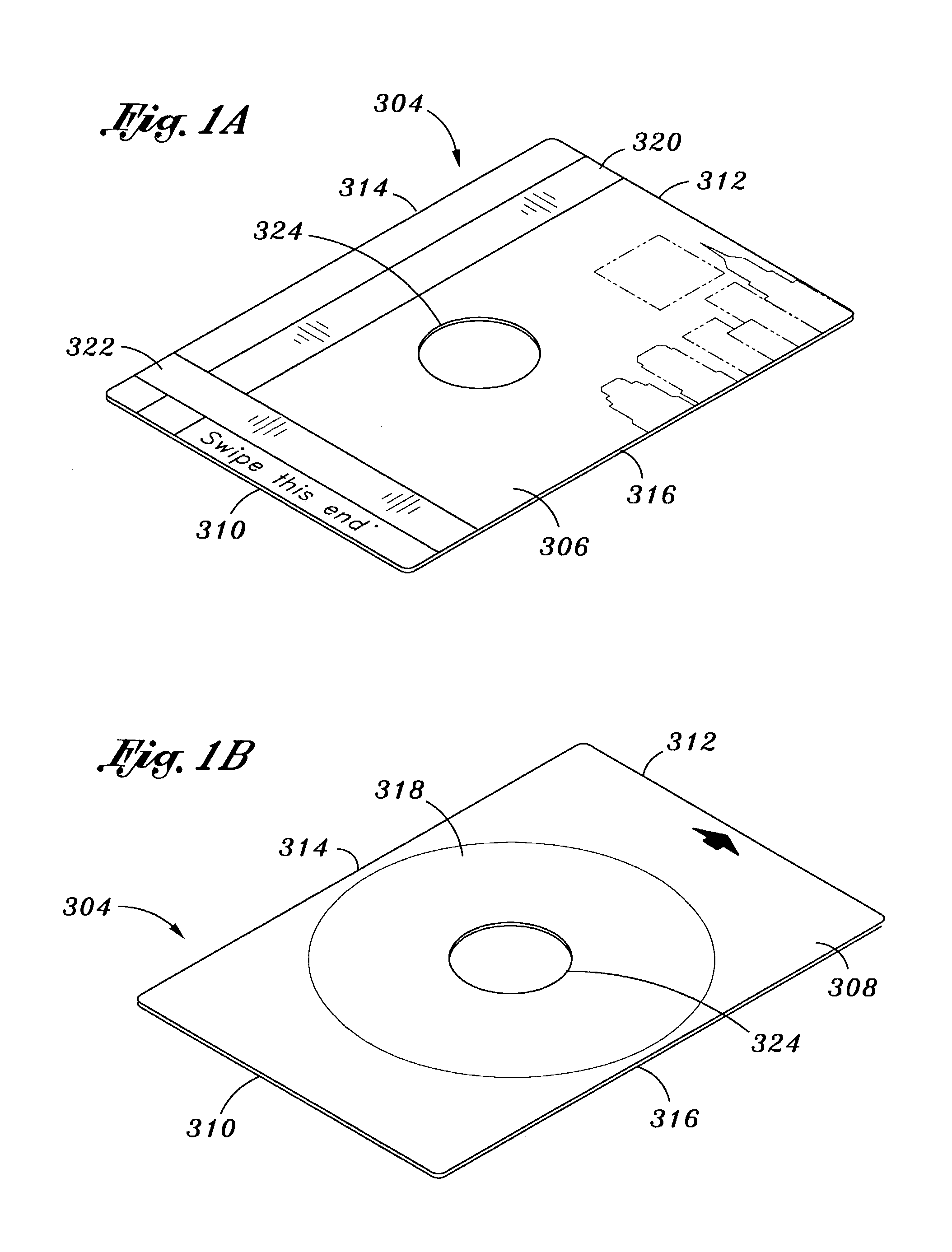
[0107]Turning now to FIGS. 24A and 24B, the covering member 400 is shown incorporated into the data storage card. In the embodiment shown, the covering member 400 is positioned such that the seal 404 is connected to the first planar surface 306 of the data storage card. In one embodiment, the seal 404 is connected to the first planar surface 306 by adhesives or other method commonly known in the art. In another embodiment, especially that in which GE HCR or GE LIM makes up the seal 404, the seal 404 itself has adhesive properties to thereby attach the seal 404 to first planar surface 306.

[0108]As such, when the covering member 400 is in its free state (FIG. 24A), the plug 402 resides within the optical carriage engaging aperture 324. In other words, the covering member 400 extends over and within the aperture 324. Thus, the aperture 324 is less likely to cause the data storage card to become jammed within a data reader. More specifically, as the data storage card is fed into a data ...


PUM


Abstract

A data storage card that includes a card body, an aperture, an optical storage region, and a magnetic storage region. The card is formed to cooperatively engage both a drive mechanism of a magnetic stripe reader and a drive mechanism of an optical data reader. In one embodiment, the card includes a resiliently displaceable cover member that automatically moves in and out of the aperture for proper use in various data readers. Also, in one embodiment, the optical data region is formed on a film to reduce the thickness of the card. Moreover, in one embodiment, the card includes a semiconductor and a counterbalance weight. Also, the card includes a spacer for abutting against components in a optical data reader in one embodiment. Finally, in one embodiment, the aperture is smaller than standard optical data discs so as to cause proper abutment against members of the optical data reader.

Description

CROSS-REFERENCE TO RELATED APPLICATIONS[0001]This application is a continuation-in-part of application Ser. No. 09 / 655,976, filed Sep. 5, 2000 now U.S. Pat. No. 6,484,940, which is herein incorporated in its entirety.STATEMENT RE: FEDERALLY SPONSORED RESEARCH / DEVELOPMENT[0002](Not Applicable)BACKGROUND OF THE INVENTION[0003]The present invention generally relates to the field of portable storage devices for electronic data, and more specifically to card-type devices having both linear magnetic and annular optical data storage regions, such data regions possessing the capability to be written at least once and read several times.[0004]As technological advances have created more powerful and sophisticated electronic equipment at astounding speeds over the years, the size of the software, programs and generated data have grown at proportionally higher rates. Technology that was once 4-bit resolution became 8-bit, which in turn became 16-bit and so forth. As a result, the need for highe...

Claims


Application Information

Patent Timeline
IPC IPC(8): G06K7/10G06K19/04G06K19/08
CPCG06K19/04G06K19/08G06K19/06075G06K19/044
Inventor DILDAY, ROBERT BURRSCARAFIOTTI, TIMOTHYGREGOR, BRETT
Owner BERKLEY JON
Why Eureka
Try Eureka