
Composite structural material and method of making same

a composite structural material and composite technology, applied in the field of composite structural materials and methods of making same, can solve the problems of increasing static strength and stiffness requirements, /or requiring greater shock and impact resistance, and general consideration of unsuitable synthetic lumber

Inactive Publication Date: 2005-12-06
CODA CAPITAL MANAGEMENT GROUP
View PDF65 Cites 103 Cited by
  • Summary
  • Abstract
  • Description
  • Claims
  • Application Information

AI Technical Summary

Benefits of technology

[0022]Suitable vitreous materials include glass, fly ash, and ceramic particles. To lighten the weight and lower the cost, hollow vitreous spheres can be used, e.g., glass or ceramic microspheres having a diameter of about 5 to 225 microns. Specific examples include Z-Light® ceramic microspheres, which are available from 3M Company and which have a bulk density of approximately 0.7 g / cc and a crush strength of about 2,000 to 3,500 psi. These come in different versions. One version that it is believed may be especially suitable is Z-Light W-1020 microspheres, which have diameters primarily in the range of about 10 to 120 microns and a crush strength of approximately 3,500 psi.
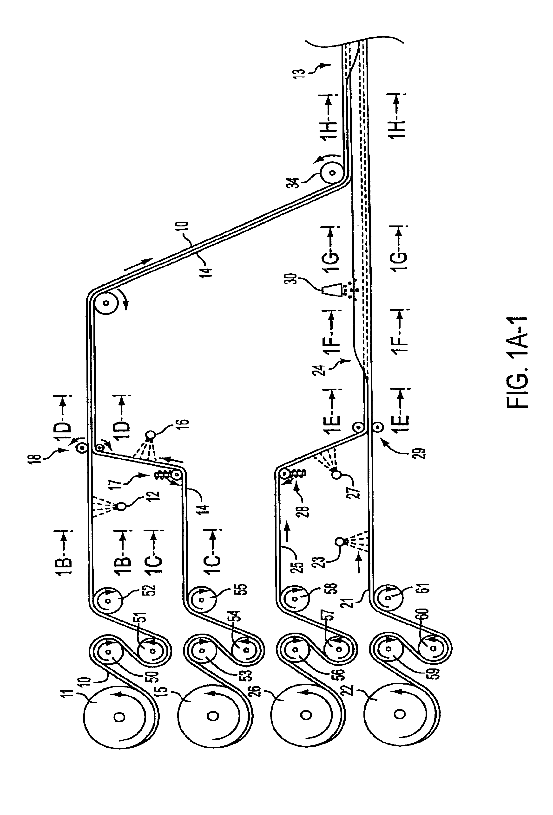
[0117]Preferably the web material is forced into its sleeve-like configuration prior to the mixture of matrix resin precursor composition and filler solid particles being deposited on the web material. The forcing of the web material into a sleeve-like configuration can be facilitated by wrapping the material around, and pulling it over, an elongated mandrel that corresponds in shape to the external die segments of the continuous molder. In this manner the mandrel imparts its shape to the web material and the external die helps to hold that shape.

Problems solved by technology

Such synthetic lumber is generally considered unsuitable, however, for uses that require it to withstand higher bending and compression loads, require increased static strength and stiffness requirements, and / or require greater shock and impact resistance.
Thus, it is generally unsuitable for use as primary structural load-bearing elements, such as posts, joists, beams, and stringers for shipping pallets.

Method used


Image

  • Composite structural material and method of making same
  • Composite structural material and method of making same
  • Composite structural material and method of making same

Examples


process example

ILLUSTRATED PROCESS EXAMPLE

[0122]The invention perhaps will be better understood by considering the following description of one way of manufacturing the new composite structural material.

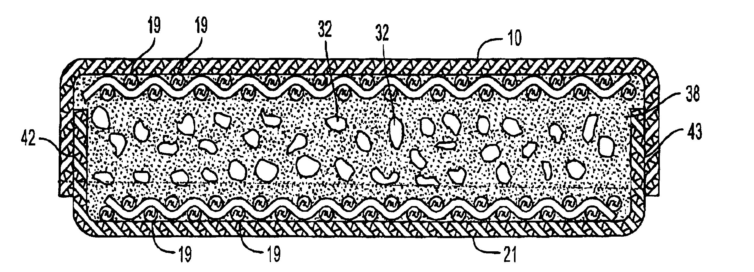
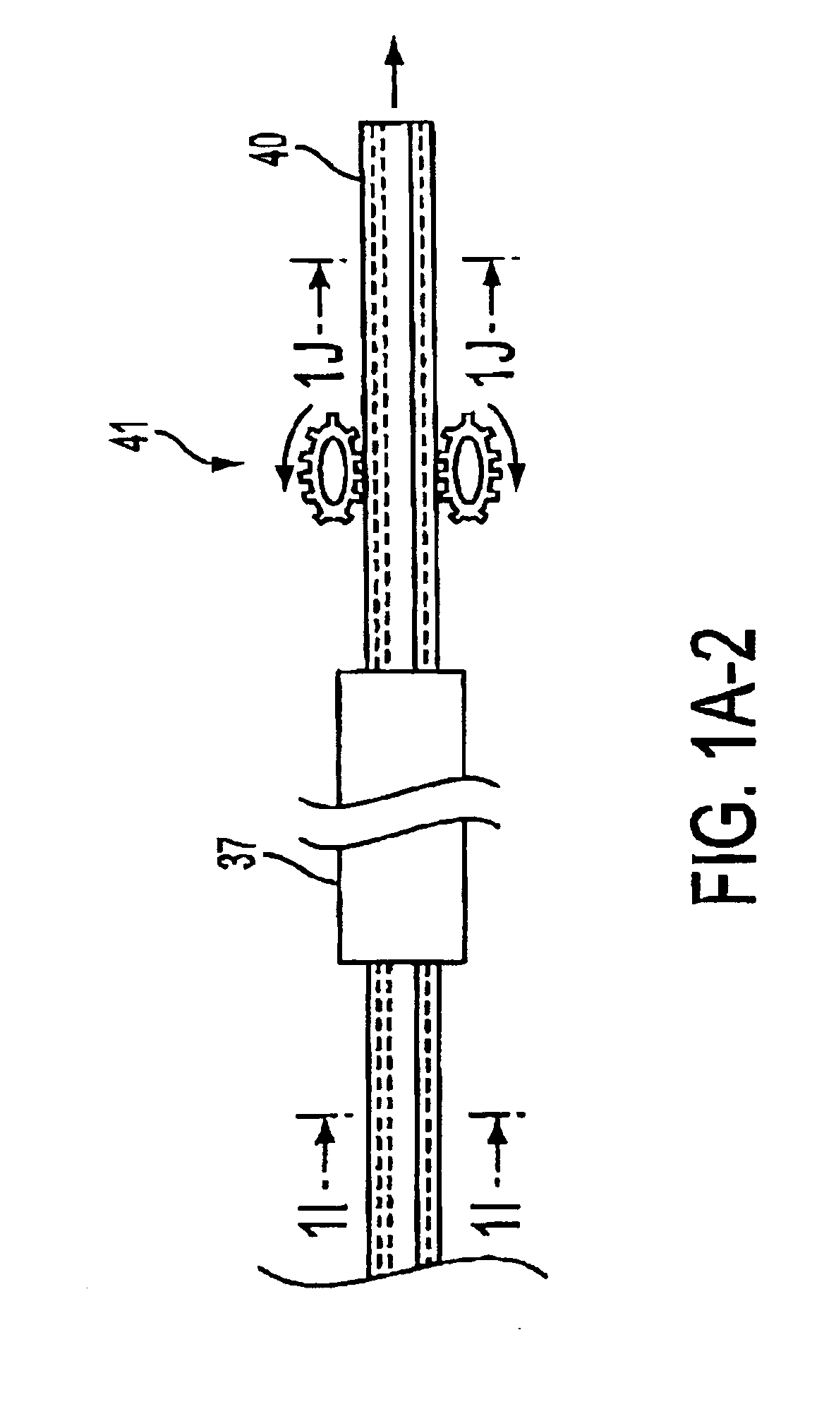
[0123]This example describes the construction of a composite board having the cross-sectional dimensions of a 1×4, i.e., ¾ inch by 3½ inches, using the C-chann method. The process is continuous and is illustrated schematically in FIG. 1. The proportions in FIG. 1 are not to actual scale. For example, for ease of illustration the thickness of papers 10 and 21 is exaggerated. So is the diameter of the warp cords 19 and the woof cords 20. And whereas the drawings depict approximately two dozen warp cords across the width of a 1×4, in actual practice there would preferably be at least 70. Also, FIGS. 1B through 1J are on a larger scale than FIG. 1A, for ease of illustrating certain details.

[0124]Referring to FIG. 1, a strip of recycled kraft paper 10 is pulled off supply roll 11, passed around guide ro...


PUM

PropertyMeasurementUnit
Fractionaaaaaaaaaa
Percent by massaaaaaaaaaa

Abstract

A composite structural material suitable, for example, as a replacement for wooden boards, is disclosed. It comprises a dimensionally stable core material ensheathed in a dimensionally stable, laminar covering that is adherent to the core material. The laminar covering is comprised of at least one layer of parallel cords bonded to at least one layer of a rigidified web material selected from the group consisting of paper and cloth. Suitable core materials include polyurethane foam, optionally filled with granulated rubber and / or expandable polymer beads. The parallel cords preferably are supplied in the form of a strip of polyester cloth, as the warp cords thereof. The web material preferably is kraft paper that is rigidified with an epoxy resin.

Description

BACKGROUND OF THE INVENTION[0001]There are many different structural materials made at least in part from synthetic resins, that are intended to be used in place of wood. An elusive goal in designing such materials is the combination of reasonable cost with relatively high strength and stiffness. Thus, for example, synthetic lumber made by hot melt extrusion of mixtures of waste wood fiber and recycled thermoplastic material such as polyethelene can be produced at a low enough cost to make them feasible for use as decking boards. Such synthetic lumber is generally considered unsuitable, however, for uses that require it to withstand higher bending and compression loads, require increased static strength and stiffness requirements, and / or require greater shock and impact resistance. Thus, it is generally unsuitable for use as primary structural load-bearing elements, such as posts, joists, beams, and stringers for shipping pallets. For those types of uses a material has to have a hig...

Claims


Application Information

Patent Timeline
IPC IPC(8): B29C44/12B32B29/00B29C44/32B29C70/50B32B5/00B32B5/08B32B5/28B32B27/40B32B29/02
CPCB29C70/50B32B5/08B32B5/28B32B27/40B32B29/02B29C44/326B29C44/1209Y10T428/233B29C2035/0811B29C2035/0855B29C2035/0861Y10T428/239Y10T428/24537Y10T428/24132Y10T428/23Y10T428/249986Y10T442/198Y10T428/249942Y10T442/3967Y10T442/3927Y10T428/249952Y10T428/31993Y10T442/3325Y10T428/249987B32B21/02
Inventor ROTH, ARTHUR J.WINTERS, PATRICK H.CLEMENT, MICHAEL H.
Owner CODA CAPITAL MANAGEMENT GROUP
Learn More