Monitoring alignment between pulse carvers and phase modulators in optical systems

a phase modulator and optical system technology, applied in the field of optical telecommunications, can solve the problems of drifting time delay of optical and electrical devices, and the inability to apply rz-dpsk systems and other problems

Active Publication Date: 2005-12-06
LUCENT TECH INC
View PDF4 Cites 25 Cited by
  • Summary
  • Abstract
  • Description
  • Claims
  • Application Information

AI Technical Summary

Problems solved by technology

However, since the time delay of optical and electrical devices can drift over time due to temperature changes or device aging, it is useful to monitor the alignment status between the pulse carver and the phase modulator during the operation of the system.
However, since a phase-modulated data signal provides constant optical power, these techniques cannot be applied for RZ-DPSK systems.

Method used


Image

  • Monitoring alignment between pulse carvers and phase modulators in optical systems
  • Monitoring alignment between pulse carvers and phase modulators in optical systems
  • Monitoring alignment between pulse carvers and phase modulators in optical systems

Examples


Embodiment Construction

[0013]Reference herein to “one embodiment” or “an embodiment” means that a particular feature, structure, or characteristic described in connection with the embodiment can be included in at least one embodiment of the invention. The appearances of the phrase “in one embodiment” in various places in the specification are not necessarily all referring to the same embodiment, nor are separate or alternative embodiments mutually exclusive of other embodiments.

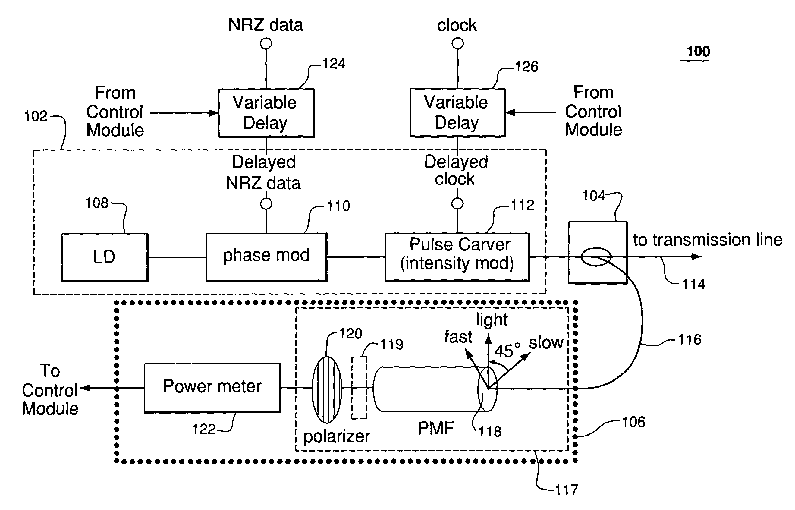
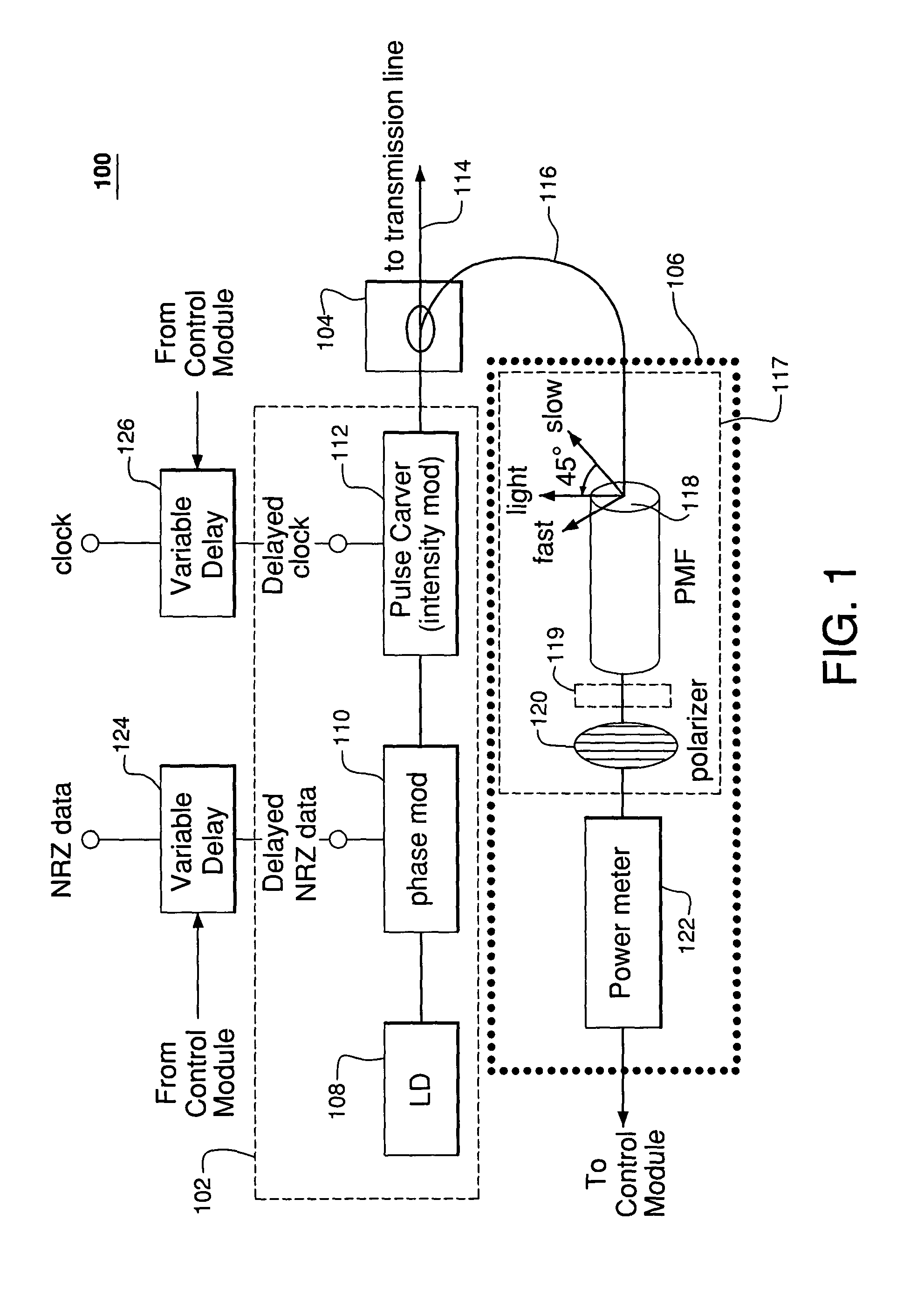
[0014]FIG. 1 depicts an optical sub-system 100 according to one embodiment of the present invention. Optical sub-system 100 includes RZ-DPSK transmitter 102, splitter 104, and alignment-monitoring module (AMM) 106. As shown, the optical output of RZ-DPSK transmitter 102 feeds splitter 104, which splits the transmitter output signal into two paths. One path (114) feeds the transmission line (e.g., an optical fiber that feeds a wavelength division multiplexer), and the other path (116) feeds AMM 106.

[0015]RZ-DPSK transmitter 102 incl...


PUM


Abstract

Timing alignment between a pulse carver (i.e., intensity modulator) and a phase modulator, e.g., in a return-to-zero (RZ) differential phase-shift keying (DPSK) optical transmitter, is monitored by filtering a signal from the transmitter and measuring the power of the filtered signal. In certain embodiments, the filter has a birefringent device (such as a polarization-maintaining fiber) and a polarizer. The polarizer may be a rotating polarizer with a rotating quarter-wave plate in front of it. In other embodiments, the filter is a periodic filter such as a Mach-Zehnder interferometer or an etalon filter. Regardless, the measured power may be used to generate control signals used to variably delay the signals that drive the phase modulator and / or the pulse carver to compensate for detected misalignment. The measured power may also be used to monitor the bit-error-rate degradation caused by timing misalignment between the pulse carver and the phase modulator.

Description

BACKGROUND OF THE INVENTION[0001]1. Field of the Invention[0002]This invention relates generally to the field of optical telecommunications and, in particular, to monitoring the alignment between phase- and amplitude-modulating elements of a phase-and-amplitude modulating optical transmitter.[0003]2. Description of the Related Art[0004]Historically, amplitude modulation, in the form of on-off keying (OOK) and return-to-zero OOK (RZ-OOK), has been the predominant form of modulation in optical communication systems. Recently, return-to-zero, differential phase-shift keying (RZ-DPSK) modulation has been proposed as an alternative to on-off keying in optical transmission systems. This is because, compared with OOK systems, RZ-DPSK systems generally offer enhanced receiver sensitivity and also generally reduce the deleterious effects of fiber nonlinearities (e.g., inter- and intra-channel cross-phase modulation). More information can be found in Atia, W. A., and Bondurant, R. S., “Demons...

Claims


Application Information

Patent Timeline
Patent Type & Authority Patents(United States)
IPC IPC(8): H04B10/155
CPCH04B10/505H04B10/5051
Inventor DOERR, CHRISTOPHER R.KIM, HOON
Owner LUCENT TECH INC
Why Eureka
Try Eureka