Long-wavelength optical fiber amplifier

a long-wavelength, optical fiber technology, applied in the direction of optics, optical elements, instruments, etc., can solve the problems of difficult tuning of the operating parameters, complex configuration of the erbium-doped fiber amplifier, noise figure and gain-flattening, etc., to reduce the momentary gain-output variation, short control time, and quick response speed

Inactive Publication Date: 2005-12-06
SAMSUNG ELECTRONICS CO LTD
View PDF7 Cites 3 Cited by
  • Summary
  • Abstract
  • Description
  • Claims
  • Application Information

AI Technical Summary

Benefits of technology

[0015]One object of the present invention is to provide a long-wavelength optical fiber amplifier that has a short control time and a swift response speed, thereby reducing the momentary gain-output variation.

Problems solved by technology

Problems related to noise figure and gain-flattening occur in erbium-doped fiber amplifiers.
Conventional gain control methods using an optical element is are known, but these method have problems in that the configuration of the erbium-doped fiber amplifiers is complicated and it is also difficult to tune its operating parameters according to the positionally conditions of the erbium-doped optical fiber amplifier.
In addition, such gain control devices also have a problem in that it needs a function to prevent the temporary overflow-phenomena of output optical signals due to increase or decrease in the number of channels.
However, such WAD optical communication networks have a problem in that input / output optical powers in the long-wavelength bands have low conversion efficiency and the noise figure is high due to low-density inversion.
However, in such conventional long-wavelength optical fiber amplifiers, which induce the second amplifying of the erbium-doped optical fiber using the first pumping light of 980 nm, a response speed delay is caused by the second pumping operation, thereby causing a control time delay Δt1, as shown in FIG. 1.
These momentary gain variations ΔP1 are accumulated during a long-distance transmission of optical light, thereby causing an optical signal error.

Method used


Image

  • Long-wavelength optical fiber amplifier
  • Long-wavelength optical fiber amplifier
  • Long-wavelength optical fiber amplifier

Examples


first embodiment

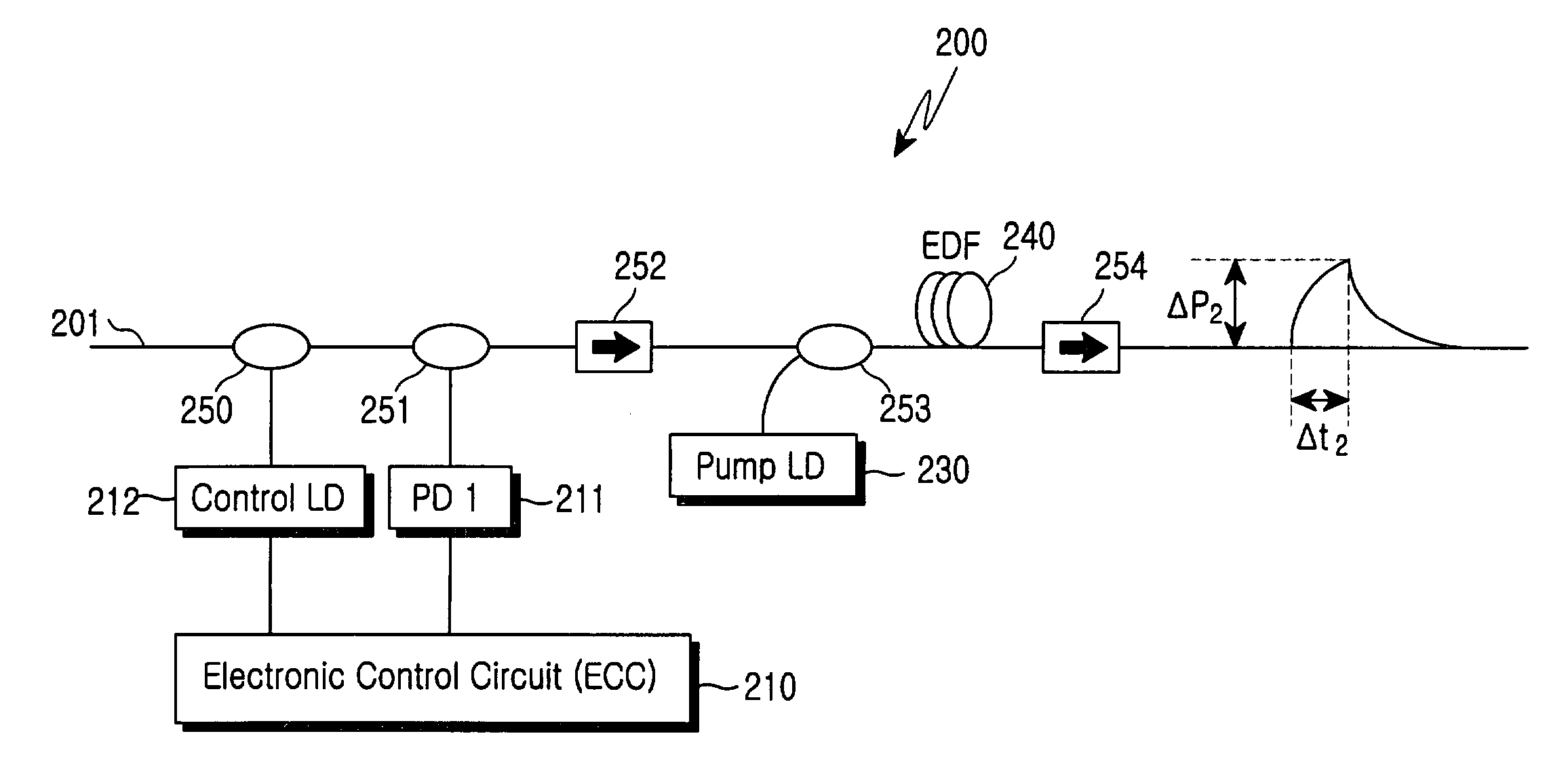
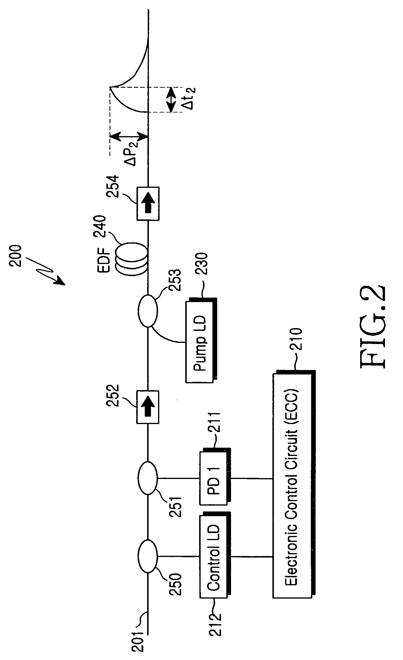
[0024]Referring to FIG. 2, in accordance with a first embodiment, a long-wavelength optical fiber amplifier 200 for amplifying a long wavelength-band input optical signal 201 includes a first pumping light source 230, a photo detector 211, an erbium-doped optical fiber 240, a second pumping light source 212, a controller 210, first and second wavelength-selective couplers 250 and 253, a beam splitter 251, and first and second isolators 252 and 254. The first pumping light source 230 generates and outputs a first pumping light of 980 nm. The photo detector 211 detects the optical intensity of the input optical signal 201. The controller 210 calculates the amount of optical-intensity loss and the number of channels of the input optical signal 201, and provides an output control signal based on the calculated result.

[0025]The input optical signal 201 travels from left to right in FIG. 2. A light traveling in the same direction as the traveling direction of the input optical signal 201 ...

second embodiment

[0035]Referring to FIG. 3, a long-wavelength optical fiber amplifier 400 according to the present invention is shown. The amplifier 400 includes first and second wavelength-selective couplers 420 and 421, first and second isolators 440 and 441, a first pumping light source 450, an erbium-doped optical fiber amplifier 430, a second pumping light source 412, a photo detector 411, and a controller 410.

[0036]A beam splitter 422 is located at the upstream side of the second isolator 440. The photo detector 411 functions to detect the intensity of an amplified optical signal output from the long wavelength optical fiber amplifier 400.

[0037]The controller 410 calculates the number of channels and the amount of optical signal loss, based on the intensity of the optical signal detected by the photo detector 411, and provides an output control signal for compensating the amount of loss of the output optical signal to the second pumping light source 412.

third embodiment

[0038]Referring to FIG. 4, a long-wavelength optical fiber amplifier 500 according to the present invention is shown. The amplifier 500 includes a beam splitter 520, a first wavelength-selective coupler 521, first and second isolators 540 and 541, a first pumping light source 550, an erbium-doped optical fiber 530, a second pumping light source 512, a second wavelength-selective coupler 522, and a controller 510. The first and second isolators 540 and 541 block a backward-traveling light that travels opposite to the traveling direction of an input optical signal 501. The erbium-doped optical fiber 530 outputs an induced-emission light in the long wavelength band. The controller 510 controls the output of the second pumping light source 512. The beam splitter 520 is located at the upstream side of the first isolator 540, splits off part of the input optical signal, and provides the split signal part to the photo detector 511.

[0039]The first wavelength-selective coupler 521 is located...


PUM


Abstract

An optical fiber amplifier is disclosed for amplifying an input optical signal in the long wavelength band. The amplifier include first and second pumping light sources, a photo detector for detecting the intensity of the input optical signal, an erbium-doped optical fiber, and a controller. The optical fiber is brought to a first-pumped state by the first pumping light output from the first pumping light source. This generates an amplified spontaneous emission in the short wavelength band. The optical fiber is brought to a second-pumped state by the amplified spontaneous emission and outputs an induced emission light in the long wavelength band. The second pumping light source outputs a second pumping light in the same wavelength band as the amplified spontaneous emission, while controlling the intensity of the second pumping light by an output control signal, thereby controlling the intensity of the second-pumped state of the optical fiber. The controller calculates the amount of optical intensity loss and the number of channels of the input optical signal, based on the detected optical intensity, and transmits the output control signal to the second pumping light source for compensating the loss of the input optical signal.

Description

CLAIM OF PRIORITY[0001]This application claims priority to an application entitled “LONG-WAVELENGTH OPTICAL FIBER AMPLIFIER”, filed in the Korean Industrial Property Office on Sep. 23, 2002 and assigned Ser. No. 2002-57537, the contents of which are hereby incorporated by reference.BACKGROUND OF THE INVENTION[0002]1. Field of the Invention[0003]The present invention relates to an optical fiber amplifier, and more particularly to a long-wavelength optical fiber amplifier including a long wavelength-band erbium-doped fiber.[0004]2. Description of the Related Art[0005]Problems related to noise figure and gain-flattening occur in erbium-doped fiber amplifiers. This has cause an increased demand for a gain control devices that automatically keep the gain of each channel uniform when there are variations in the number of input channels or in the input optical intensity. Conventional gain control methods using an optical element is are known, but these method have problems in that the conf...

Claims


Application Information

Patent Timeline
Patent Type & Authority Patents(United States)
IPC IPC(8): H01S3/06G02B6/00H01S3/0933H01S3/094H01S3/13
CPCH01S3/094003H01S3/1301H01S3/094011H01S3/094023H01S3/0677H01S3/10015H01S3/1608G02B6/00
Inventor HWANG, SEONG-TAEKSHIN, HONG-SEOKKANG, BYUNG-CHANG
Owner SAMSUNG ELECTRONICS CO LTD
Why Eureka
Try Eureka