Composite flexible wiring board, method of manufacturing the same, electro-optical device, and electronic equipment

a flexible wiring board and flexible technology, applied in the direction of identification means, instruments, printed circuit non-printed electric components, etc., can solve the problems of preventing the reduction of the weight and thickness of the liquid crystal display device and the electronic equipment, and achieve the effects of easy manufacturing, high efficiency and easy formation

Active Publication Date: 2005-12-06
BOE TECH GRP CO LTD
View PDF13 Cites 70 Cited by
  • Summary
  • Abstract
  • Description
  • Claims
  • Application Information

AI Technical Summary

Benefits of technology

[0018](a) Since the first and second flexible wiring boards are joined to each other in superimposed relation, wiring layers and electronic parts can be distributed to the two flexible wiring boards. Accordingly, a packing density per unit area of the composite flexible wiring board can be increased, thus resulting in higher flexibility in design.
[0043]The electro-optical device and the electronic equipment according to the present invention each include the composite flexible wiring board according to the present invention, and hence can be reduced in size and weight as a result of the working advantages obtainable with the composite flexible wiring board.

Problems solved by technology

Thus, the presence of the printed board 3 has impeded a reduction in weight and thickness of the liquid crystal display device and the electronic equipment.

Method used


Image

  • Composite flexible wiring board, method of manufacturing the same, electro-optical device, and electronic equipment
  • Composite flexible wiring board, method of manufacturing the same, electro-optical device, and electronic equipment
  • Composite flexible wiring board, method of manufacturing the same, electro-optical device, and electronic equipment

Examples


second embodiment

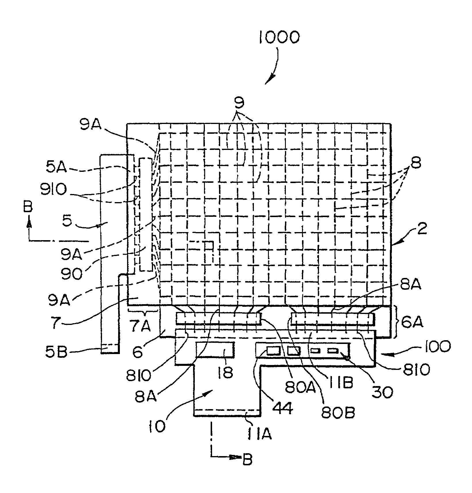
[0082]In a second embodiment, a description will be made of a liquid crystal display device as one example of electro-optical devices to which the flexible wiring board according to the present invention is applied. FIG. 5 is a plan view schematically showing a liquid crystal display device 1000 according to this embodiment, and FIG. 6 is a schematic sectional view taken along line B—B in FIG. 5.

[0083]The liquid crystal display device 1000 is constructed as, for example, a reflective type liquid crystal display device of the passive matrix addressing type. The liquid crystal display device 1000 comprises a liquid crystal display panel 2, a composite flexible wiring board 100 according to the present invention, and a known flexible wiring board 5. In the example shown in FIG. 5, the composite flexible wiring board 100 is the same as that according to the first embodiment. Therefore, components having the same functions as those of the composite flexible wiring board 100 according to ...

first embodiment

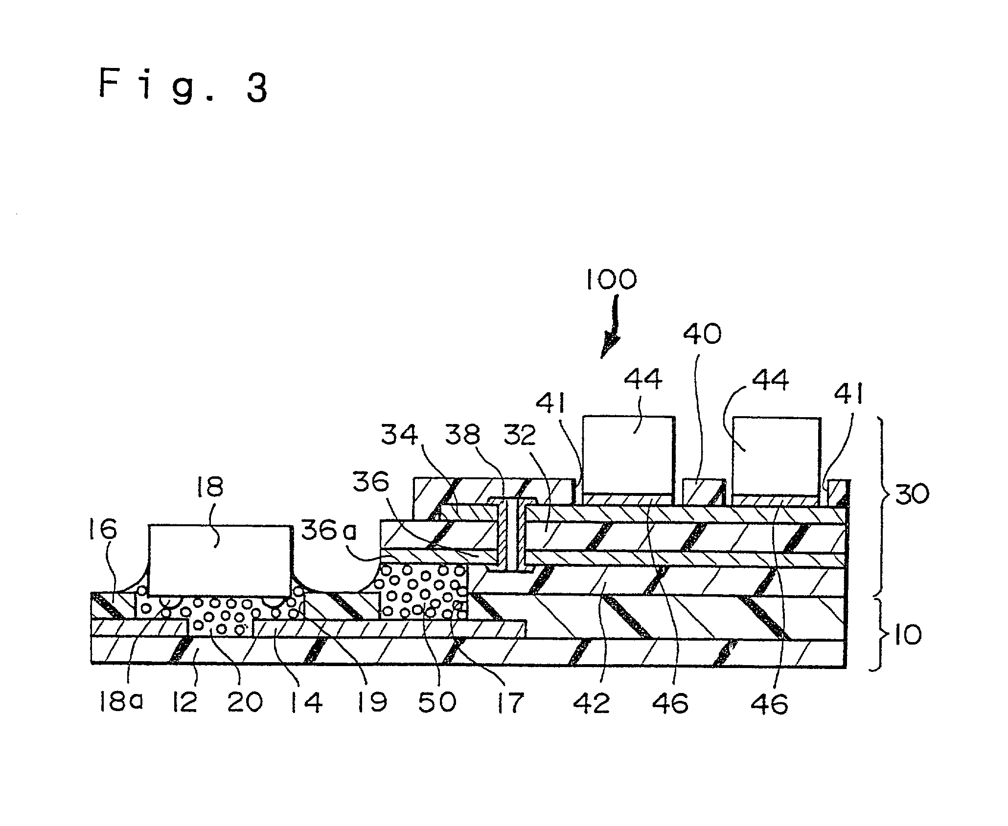
[0092]The first flexible wiring board 10 comprises a first single-sided flexible board 110, a second single-sided flexible board 120, and an anisotropic conductive layer 140 is interposed between the first single-sided flexible board 110 and the second single-sided flexible board 120. As with the first embodiment, the first flexible wiring board 10 has the same planar shape as the overall planar shape of the composite flexible wiring board 200, and also includes an input terminal region and an output terminal region (both not shown).

[0093]The first single-sided flexible board 110 comprises a base 112 being dielectric and flexible, and a wiring layer 114 having a predetermined pattern and formed on a lower surface of the base 112. An insulating layer 118 is formed on the lower side of the base 112 so as to cover the wiring layer 114. Further, in a predetermined area of the base 112, a hole is formed for constituting a contact portion. A conductive layer 116a is formed in the hole, an...

fourth embodiment

[0099]FIGS. 8 and 9 show a modification of the composite flexible wiring board according to the present invention. FIG. 8 is a plan view schematically showing a composite flexible wiring board 300, and FIG. 9 is a schematic sectional view taken along line C—C in FIG. 8. Components in this fourth embodiment having essentially the same functions as those of the composite flexible wiring board 100 described above are denoted by the same symbols and a detailed description thereof is omitted here.

[0100]The composite flexible wiring board 300 of this fourth embodiment is constructed by joining an additional single-sided flexible wiring board 60 to the composite flexible wiring board 100 of this first embodiment. The single-sided flexible wiring board 60 constitutes a branched wiring unit and has a second output terminal region 61B formed at its free end.

[0101]Next, a sectional structure of a joint portion between the composite flexible wiring board 300 and the single-sided flexible wiring...


PUM

PropertyMeasurementUnit
temperatureaaaaaaaaaa
flexibleaaaaaaaaaa

Abstract

A composite flexible wiring board comprises a first flexible wiring board and a second flexible wiring board on which a surface-mounted part is provided. The second flexible wiring board is disposed on the first flexible wiring board in its predetermined area. The first flexible wiring board and the second flexible wiring board are electrically connected to each other through an interlayer contact portion provided in a predetermined position. The first flexible wiring board has an input terminal region and an output terminal region with a power IC chip mounted on the first flexible wiring board.

Description

BACKGROUND OF THE INVENTION[0001]1. Technical Field of the Invention[0002]The present invention relates to a composite flexible wiring board including a flexible wiring board on which surface-mounted parts are disposed, and a method of manufacturing the composite flexible wiring board. The present invention also relates to an electro-optical device and electronic equipment to which the composite flexible wiring board is applied.[0003]2. Description of the Related Art[0004]Recently, display devices have been widely employed as information display terminals in portable equipment, homes, offices and factories, automobiles, etc. In particular, liquid crystal display devices have advantageous features such as thin thickness, light weight, low voltage, and low power consumption. Liquid crystal display devices are primary units of, e.g., electronic displays and have been increasingly applied to PDAs (Personal Digital Assistants), etc. by utilizing the feature of low power consumption.[0005...

Claims


Application Information

Patent Timeline
Patent Type & Authority Patents(United States)
IPC IPC(8): G02F1/1345G02F1/13G02F1/1333G09F9/00H05K1/14H05K1/18H05K3/28H05K3/32H05K3/36H05K3/46
CPCH05K1/141H05K3/361G02F1/13452H05K1/181H05K1/189H05K3/28H05K3/321H05K3/323H05K3/368H05K2201/0367H05K2201/10136G02F1/1333
Inventor OISHI, EIJIENDO, KOGO
Owner BOE TECH GRP CO LTD
Why Eureka
Try Eureka