
Eureka
For R&D, Eureka makes reading and utilizing patents & technical documents easy.
Eureka AIR
Designed for self-driven R&D workflows. Generate viable solutions, solve complex R&D challenges, empower your innovation with AI.

Eureka Materials
Designed for material experts only. Revolutionize your material R&D, from search, analyze, to developing new materials.

TechResearch
Generate reliable direction feasibility study reports for your R&D in just a few steps.

TechSeek
Discover and master advanced knowledge NOW. Basics, ideas, possibilities, all at once.

TechMind
As an expert in R&D Theories, TechMind can generates customized viable solutions instantly.

TechRisk
Analyze your overall solution with one click, know your potential R&D risks in advance.

TechMonitor
Get weekly tech updates, stay abreast of the latest tech innovations and key insights.
Measuring method and device, machine tool having such device, and work processing method
- Summary
- Abstract
- Description
- Claims
- Application Information
AI Technical Summary
Benefits of technology
Problems solved by technology
Method used
Image

Examples
first embodiment
[0125]the invention will be described below with reference to the accompanying drawings.
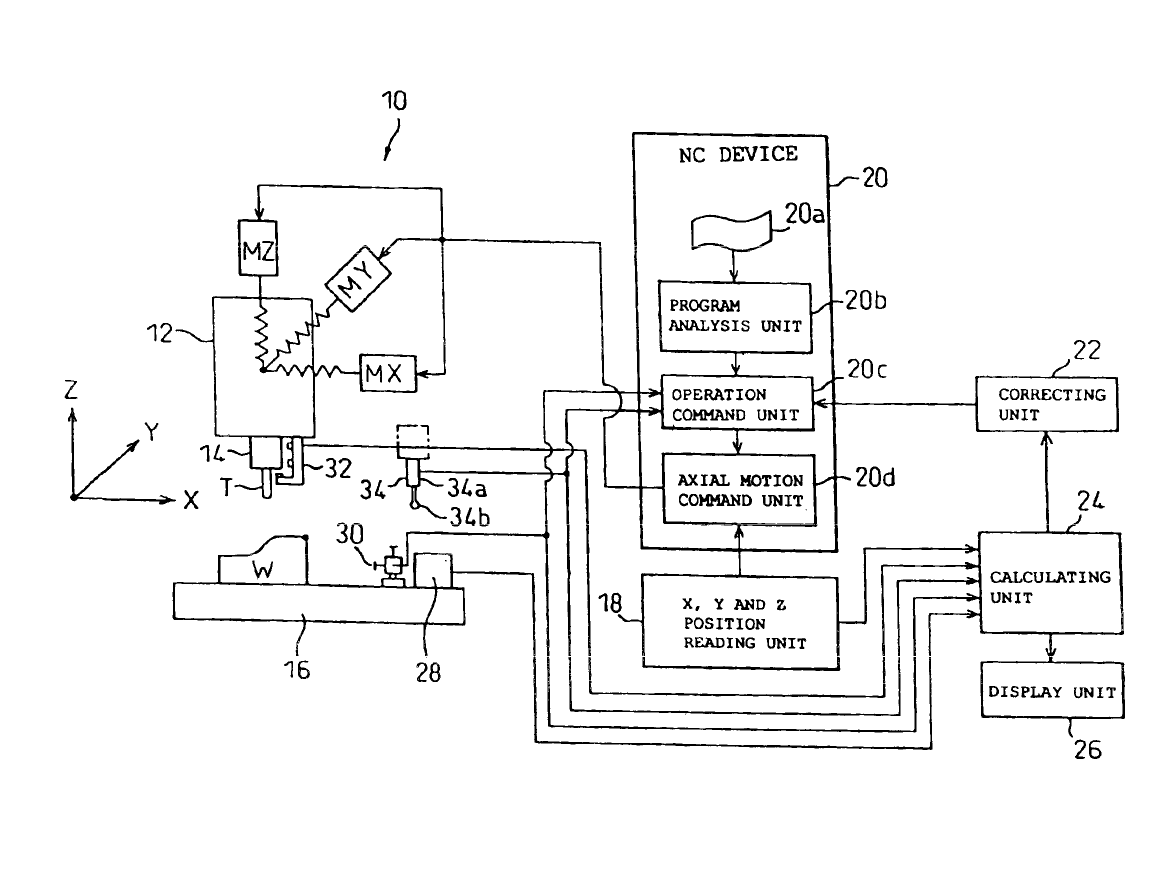
[0126]In FIG. 1, a machine tool unit 10 of an NC machine tool according to the first embodiment includes a spindle unit 12 having a spindle 14 rotatably supported and built in a spindle housing. The spindle unit 12 is movable in three orthogonal directions of X, Y and Z relatively to a table 16 with a workpiece W fixed thereon by an X-axis feed motor MX, a Y-axis feed motor MY and a Z-axis feed motor MZ, respectively. A tool T is mounted at the forward end of the spindle 14. The workpiece W is cut by rotating the tool T and machined to a desired shape while being moved along the X-, Y- and Z-axes relatively.
[0127]An NC device 20 for controlling the relative movement of the spindle unit 12 and the table 16 of the machine tool unit 10 along the X-, Y- and Z-axes includes, as main component elements, a program storage unit 20a for storing a machining program, a tool edge position measuring program, ...
second embodiment
[0158] described below, the correction value is updated every moment by measuring the displacement of the center position of the spindle 14 while the workpiece is being machined.
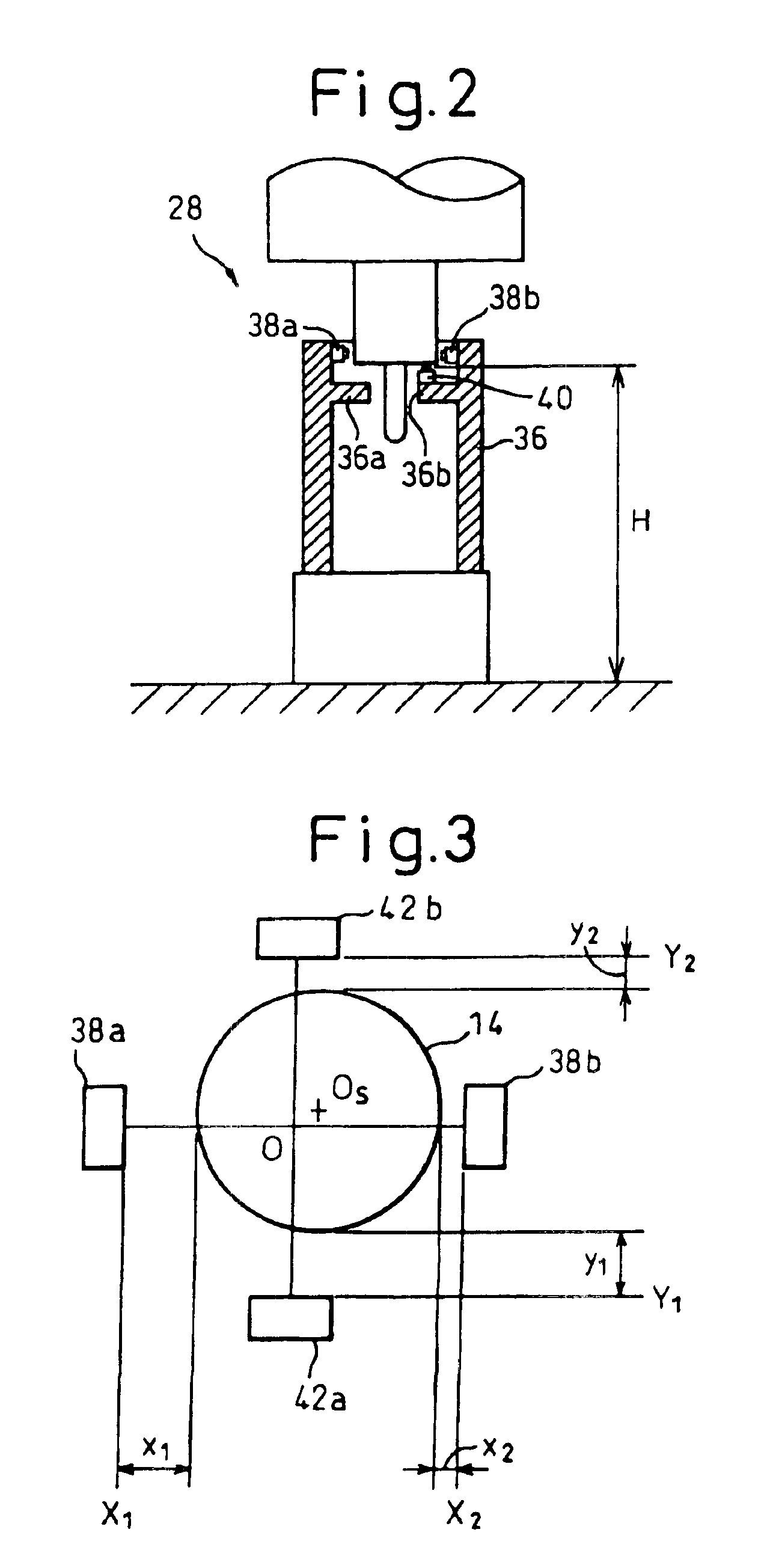
[0159]Referring to FIGS. 1 and 7, according to the second embodiment, the machine tool unit 10 includes a second spindle reference position measuring unit 32 in addition to the first spindle reference position measuring unit 28 and the tool edge position measuring unit 30. The second spindle reference position measuring unit 32 includes a frame unit 44 mounted on the end surface of the housing of the spindle unit 12 adjoining the forward end portion of the spindle 14 and a plurality of distance sensors 48a, 48b, 48c, 48d, 50 mounted on the inside of the frame unit 44. A support portion 46 extending radially inward of the spindle 14 is arranged at the forward end (the lower end in the drawing) of the frame unit 44. Also, the frame unit 44 is so shaped as not to adversely affect the measurement of the center p...
third embodiment
[0163]The embodiments described above assume that the workpiece W is accurately set in position on the machine coordinate system on the table 16. In the invention described below, however, the arrangement of the workpiece W on the machine coordinate system is also taken into account.
[0164]According to the third embodiment, a workpiece reference position measuring unit 34 (FIG. 1) is provided for measuring the reference position of the workpiece W with respect to the spindle 14. The workpiece reference position measuring unit 34 includes an axial portion 34a extending in longitudinal direction and a measuring probe 34b arranged at the forward end of the axial portion 34a. The axial portion 34a of the workpiece reference position measuring unit 34 is adapted to be mounted in a tool mounting hole (not shown) of the spindle 14. As indicated by a two-dot chain in FIG. 1, the axial portion 34a is mounted in the tool mounting hole according to a procedure similar to that for automatic tool...
PUM
 Abstract
Description
Claims
Application Information
 - R&D Engineer
- R&D Manager
- IP Professional
- Industry Leading Data Capabilities
- Powerful AI technology
- Patent DNA Extraction
Browse by: Latest US Patents, China's latest patents, Technical Efficacy Thesaurus, Application Domain, Technology Topic, Popular Technical Reports.
© 2024 PatSnap. All rights reserved.Legal|Privacy policy|Modern Slavery Act Transparency Statement|Sitemap|About US| Contact US: help@patsnap.com