Distributed refrigeration system for a vehicle

Inactive Publication Date: 2005-12-13
WHIRLPOOL CORP
View PDF8 Cites 120 Cited by
  • Summary
  • Abstract
  • Description
  • Claims
  • Application Information

AI Technical Summary

Benefits of technology

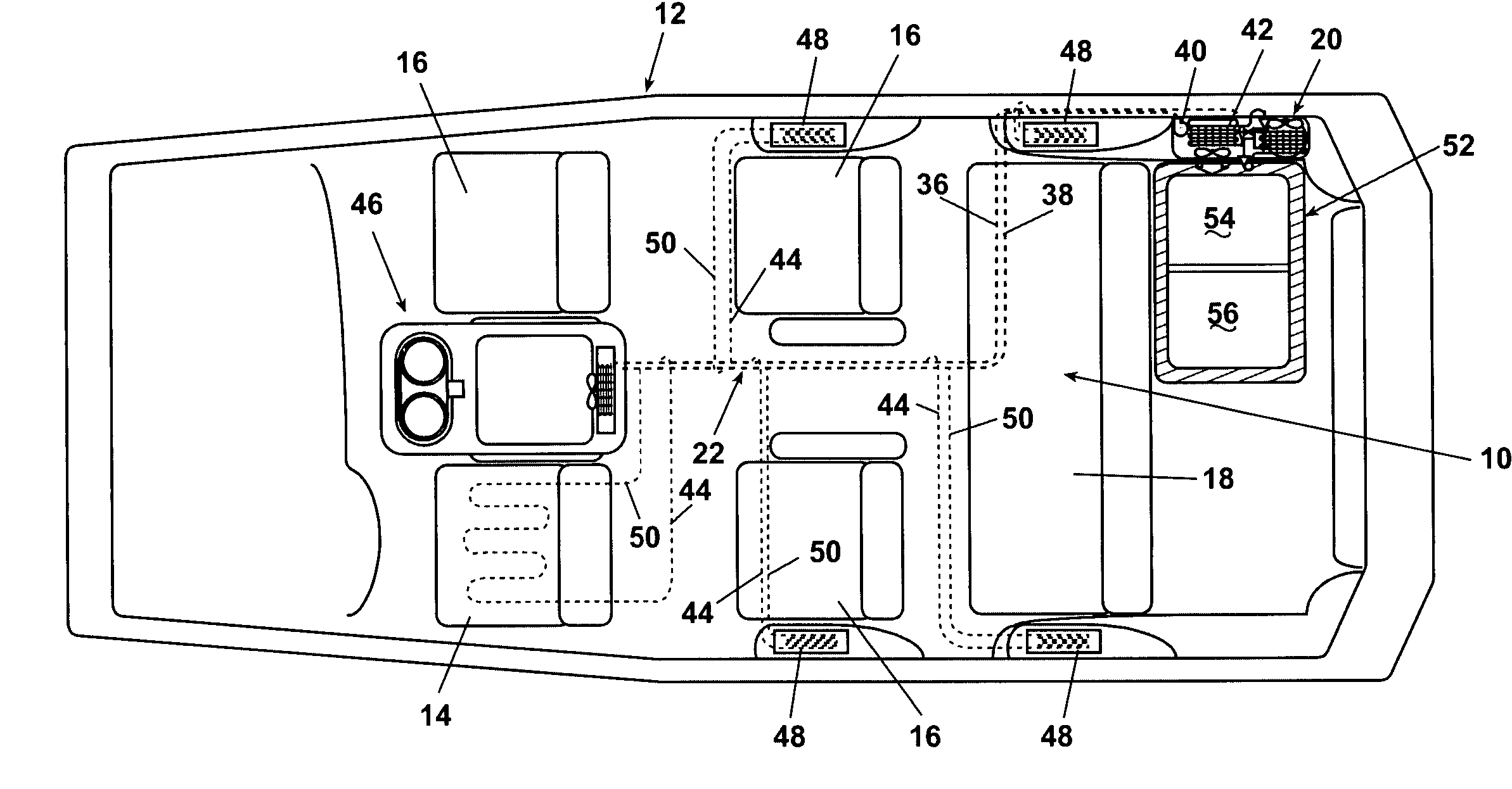
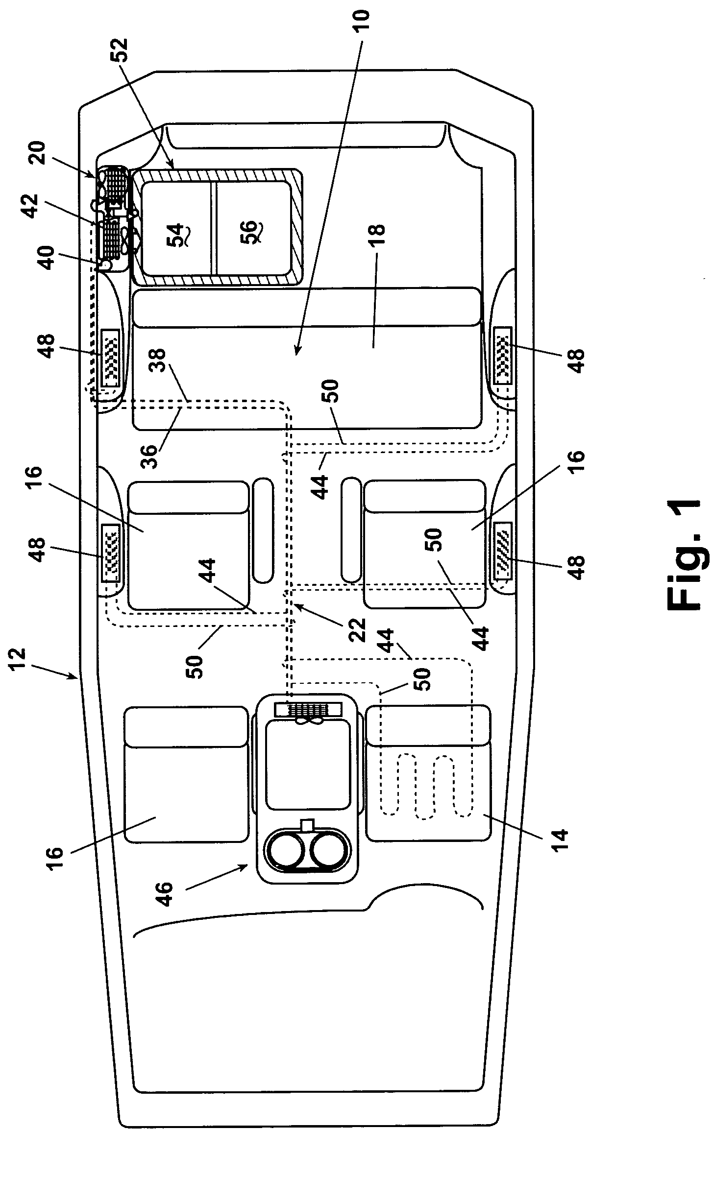
[0011]Another aspect of the invention has a cold storage compartment that can be selectively docked to one of the cooling systems in the vehicle. Also, the col

Problems solved by technology

There are limitations to the foregoing systems, however.
Moreover, the coolant normally found in vehic

Method used


Image

  • Distributed refrigeration system for a vehicle
  • Distributed refrigeration system for a vehicle
  • Distributed refrigeration system for a vehicle

Examples


Example

[0042]A second embodiment is shown in FIG. 5. Here, the primary cooling circuit 20 has a single evaporator 30 forming part of a single tube-in-tube heat exchanger. In the secondary cooling circuit 22, however, a second fluid pump 66 delivers cooled liquid from the main supply line 36 to a fin-tube heat exchanger 68 in parallel to the delivery of cooled fluid to the console 46 and to any docking stations (not shown in FIG. 5). The main cold storage compartment 52 receives cooled air either by direct vent or by insulated lines from the fin-tube heat exchanger 68.

Example

[0043]A third embodiment is shown in FIG. 6. Here, the evaporator 30 of the primary cooling circuit 20 is part of a fin-tube heat exchanger 70 with a secondary coil 72 embedded in the fins along with a primary coil 74 carrying the primary cooling circuit refrigerant. The secondary coil 72 is part of the secondary cooling circuit 22. The evaporator fan 32 blows air across the fin-tube heat exchanger 70 and delivers the cooled air either by direct vent or by insulated lines to the main cold storage compartment 52. The exchanger 70 is preferably a tube within a tube exchanger with the refrigerant from the primary circuit flowing through the inside tube.

Example

[0044]FIG. 7 shows a fourth embodiment where an automobile air conditioner circuit 76 is modified to work with a secondary cooling circuit 78 to provide a distributed refrigeration system according to the invention. The conditioner circuit 76 comprises a compressor 80, driven by the vehicle engine, and a condenser 82 with a condenser fan 84. A conventional expansion device 86 is separated from the condenser 82 by a solenoid valve 88. A refrigerator expansion device 90 is disposed in the circuit in parallel with the expansion device 86. Both expansion devices 86, 90 are connected to an air conditioner evaporator 92. When the solenoid valve 88 is open, nearly all the refrigerant flows through the usual air conditioner expansion device 86, and the evaporator 92 runs under usual air conditioner conditions. When the solenoid valve 88 is closed, the refrigerant flows through the more restrictive refrigerator expansion device 90 and the evaporator 92 runs under refrigeration conditions. Th...


PUM


Abstract

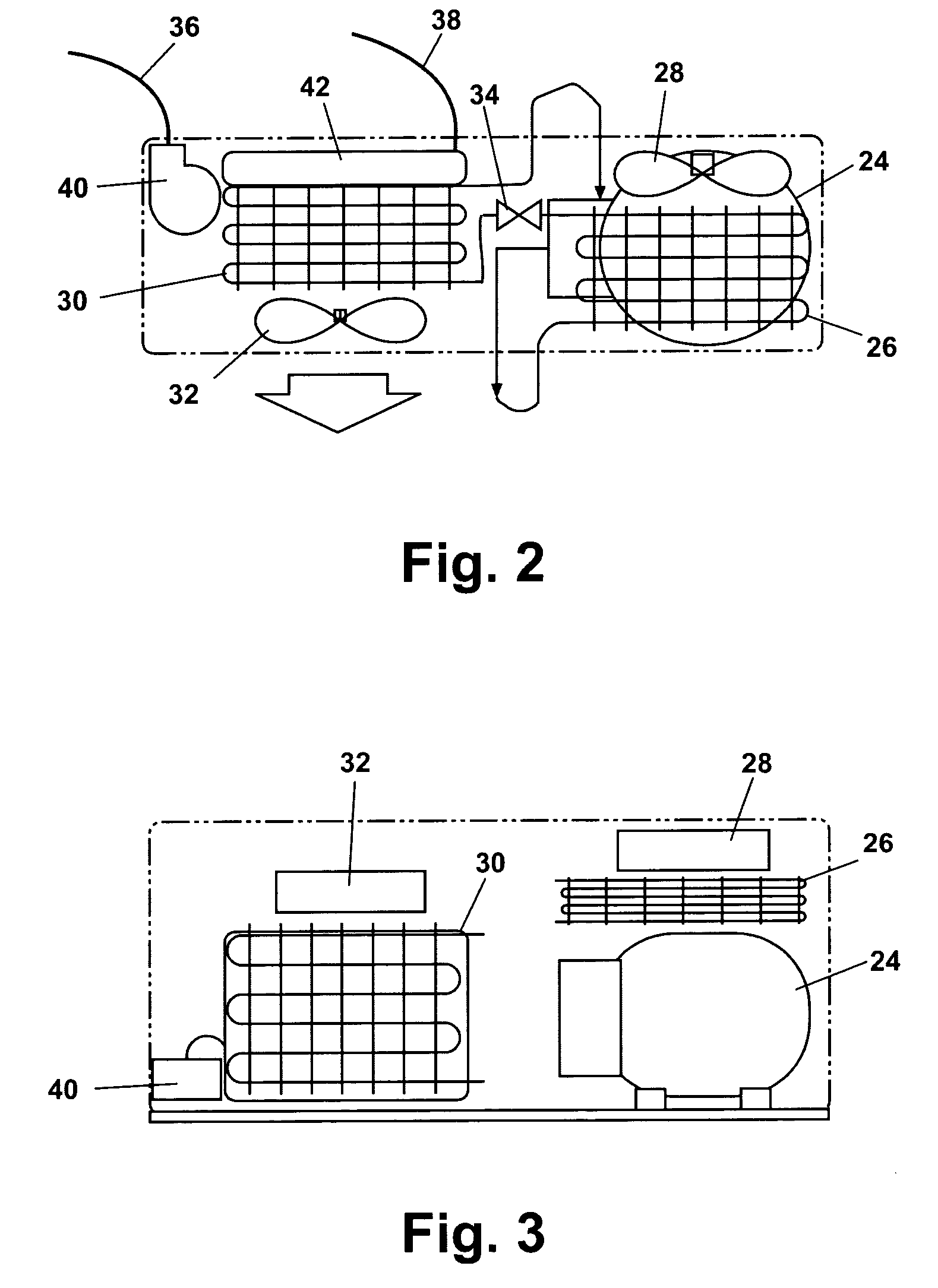
A distributed refrigeration system for a vehicle includes a vapor compression primary cooling circuit and a separate secondary cooling circuit. The secondary cooling circuit utilizes a non-toxic cooling fluid that is pumped to remote locations in the vehicle through designated supply lines. A heat exchanger acting with the primary cooling circuit cools the cooling fluid. A portable main storage compartment is fluidly connectable to the primary or secondary cooling circuits. The portable main cold storage compartment can be expandable. At the remote locations in the vehicle, docking stations permit items to be selectively cooled by the secondary cooling circuit. Both the primary and secondary cooling circuits can operate independently of the vehicle engine.

Description

[0001]This application claims the benefit of provisional application 60 / 319,501, filed Aug. 27, 2002.BACKGROUND OF INVENTION[0002]1. Field of the Invention[0003]The invention relates to a refrigeration system for a vehicle including a passenger motor vehicle. More particularly, the invention relates to a vapor compression refrigeration system that distributes coolant to remote locations in a vehicle for cooling specific stations. Other aspects of the invention include portable compartments including expandable compartments for docking to the refrigeration system.[0004]2. Description of the Related Art[0005]Refrigeration of items in a vehicle such as a passenger automobile has traditionally been accomplished by the use of portable insulated coolers. It is known to incorporate cooling units within such portable coolers, and to connect such portable coolers to an automobile air conditioning system. U.S. Pat. No. 3,850,006 describes a portable cooler having a cooling unit disposed centr...

Claims


Application Information

Patent Timeline
IPC IPC(8): B60H1/00B60H1/32B60N2/56F25B25/00F25D15/00F25D17/02F25D17/04F25D17/06
CPCB60H1/00592B60H1/323B60N2/5628F25D15/00F25D17/02B60H2001/00928F25B25/005F25D17/045F25D17/06F25D2317/0666F25D2331/801F25D2331/804F25D2400/06F25D2400/38B60H1/32281
Inventor KUEHL, STEVEN J.SLONE, CAROLYN L.LECLEAR, DOUGLAS D.TROMBLEE, JON D.
Owner WHIRLPOOL CORP
Why Eureka
Try Eureka