Fluid injection system

a technology of injection system and flue, which is applied in the direction of liquid dispensing, multi-way valve, special dispensing means, etc., can solve the problems of large cost of providing and servicing these filters, especially in subsea environments, and the size of the orifice is small, so as to reduce the average flow rate, increase the flow rate, and reduce the flow rate

Inactive Publication Date: 2005-12-13
WATSON RICHARD R
View PDF8 Cites 51 Cited by
  • Summary
  • Abstract
  • Description
  • Claims
  • Application Information

AI Technical Summary

Benefits of technology

[0010]The controller may decrease the valve opening temporarily to reduce the flow rate, to compensate for an increased flow rate during cleaning. Alternatively, the controller may selectively pause prior to reversing the position of the multi-position valve, to decrease the average flow rate from the metering body to the injection point.

Problems solved by technology

A major disadvantage of this type of system stems from the small orifice size required.
An orifice this small is easily clogged by contaminants.
Some prior art includes flow filters to prevent clogging, but providing and servicing these filters, especially in subsea environments, is expensive.
An associated disadvantage of this type of system is thus the need for a separate damping fluid, along with increased parts, such as two separate cylinders each housing separate fluid barriers.
A system with two cylinders and fluid barriers is inherently more prone to failure than a system with fewer parts.
Another disadvantage is the risk of mixing the damping fluid with and contaminating the chemical fluid to be delivered.
Another complication of existing systems in general is that using a small orifice increases the need to verify flow rate data provided by flow control devices.
These devices operate over a narrow range and are therefore limited in application.
This further increases the cost of chemical injection systems.

Method used


Image

  • Fluid injection system
  • Fluid injection system
  • Fluid injection system

Examples


Embodiment Construction

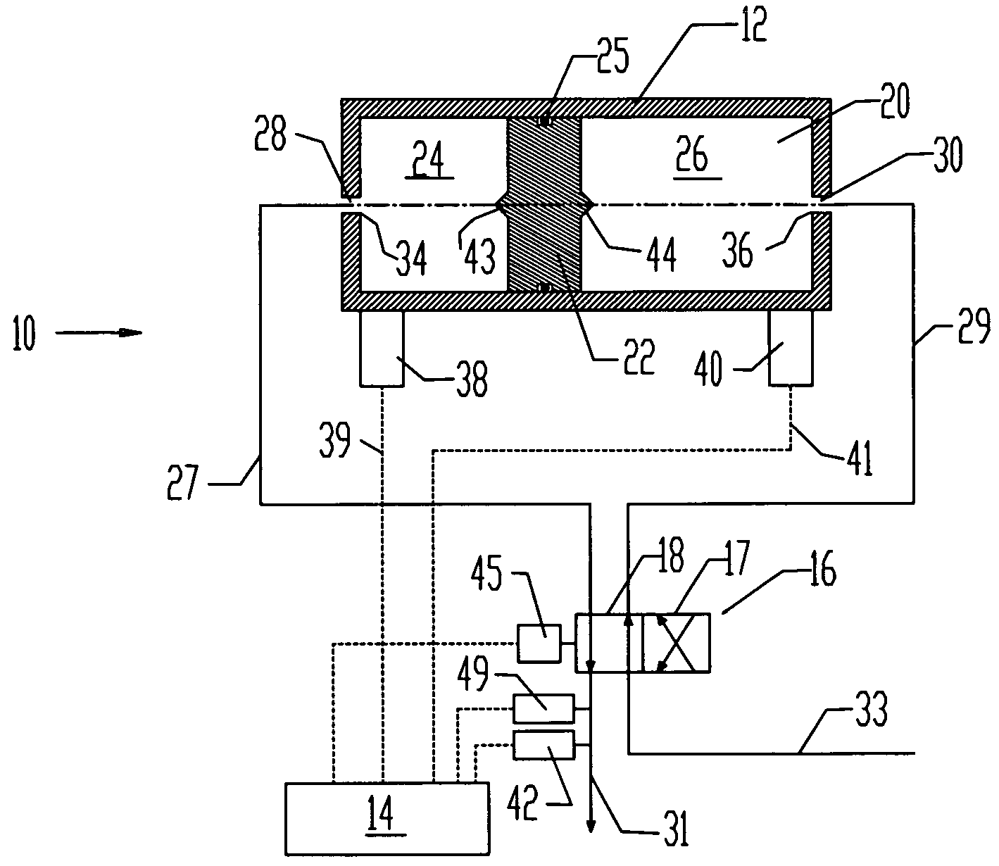
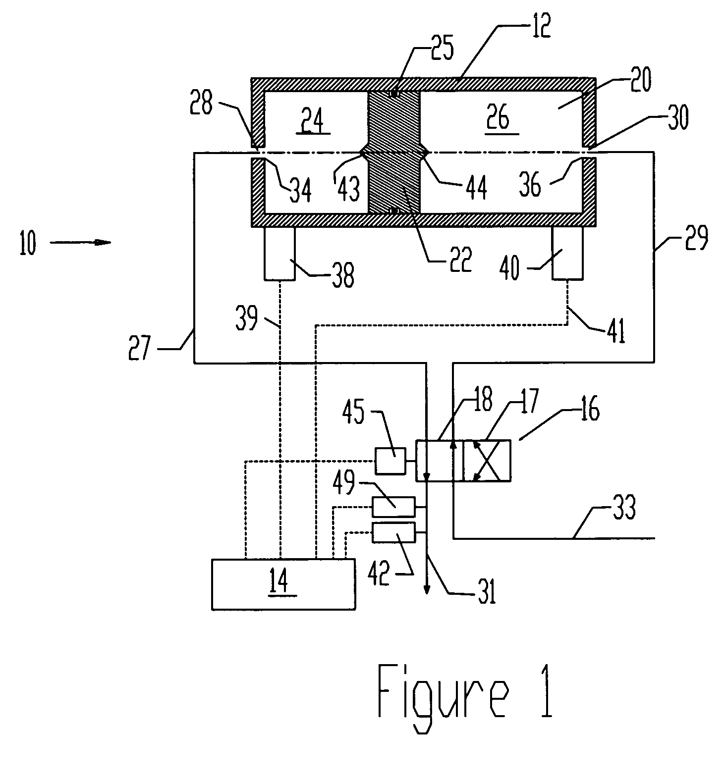
[0021]FIG. 1 schematically illustrates details of a metering body 12 interconnected with a control system 14 and a multi-position valve 16 in a chemical injection system 10. The metering body 12 has a bore 20 for containing chemical fluid to be delivered to a well. An axially movable fluid barrier 22 in the bore 20 divides the metering body 12 into variable-volume first and second chambers 24, 26. The fluid barrier 22 seals with the metering body 12 with a sealing member such as O-ring 25. The metering body 12 and the fluid barrier 22 conventionally comprise a cylinder and piston assembly, as shown. First and second input-output ports 28, 30 are provided for passing fluid into and out of first and second chambers 24, 26. Supply line 33 supplies chemical fluids at high pressure through the multi-position valve 16 to the metering body 12.

[0022]In a first valve position shown in FIG. 1, illustrated conceptually by alignment of parallel line segments 18 with lines 31 and 33, fluid passe...


PUM


Abstract

A fluid injection system controls the distribution of fluid from a supply line to a selected well at an adjustable rate. A fluid barrier divides a cylinder into first and second chambers. A multi-position valve comprises a first position for passing fluid from the supply line into the first chamber to displace fluid from the second chamber back through the valve to an injection point, and a second position for passing fluid from the supply line to the second chamber to displace fluid from the first chamber back through the valve to the injection point. A control system in communication with a position sensor times displacement of the fluid barrier to selected positions, and selectively adjusts a variable valve opening to adjust flow rate, switch between the first and second positions, and periodically increase the valve opening for cleaning.

Description

FIELD OF THE INVENTION[0001]This invention relates to a fluid injection system for controlling the distribution of fluid from a supply line to a selected well at an adjustable rate. More particularly, the present invention relates to systems and methods for controlling injection rates over a wide flow range, while preventing problems associated with the use of small flow orifices.BACKGROUND OF THE INVENTION[0002]The efficient production of oil and gas from subsea wells requires the injection of various treatment chemicals to maintain the desired composition of well fluid by controlling variables such as corrosion, scale, paraffin, emulsion, and hydrates. Often, several wells are located near each other within a producing field, but at significant distance from a surface pumping station from which chemicals are pumped. In many instances wells are offset from the pumping station by more than 10 miles, and at depths of more than 900 feet. Reliable methods and systems are therefore requ...

Claims


Application Information

Patent Timeline
Patent Type & Authority Patents(United States)
IPC IPC(8): E21B33/068G01F11/06
CPCE21B33/068G01F11/06Y10T137/7761Y10T137/86558Y10T137/8242Y10T137/0318Y10T137/7759Y10T137/86397
Inventor WATSON, RICHARD R.
Owner WATSON RICHARD R
Why Eureka
Try Eureka